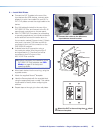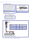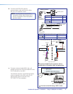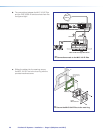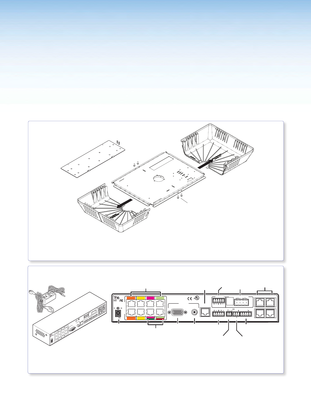
Stage 4:
Installing the PMK 550
and the PVS 305SA IP
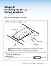
Stage 4 Involves Installing the Devices Shown Below.
LR
LR
LR
AUX AUDIO
INPUT 5
LINE OUT
VOICELIFT
RECEIVER
PAGING
SENSOR
DO NOT
GROUND
OR SHORT
SPEAKER
OUTPUTS
1B RGB
1A RGB
2B RGB
2A RGB
3B RGB
/VIDEO
4B RGB
/VIDEO
3A RGB
4A RGB
I
N
P
U
T
S
RS-232 MLC/IR
2/4/8
Ohms
CLASS 2 WIRING
AMPLIFIED AUDIO OUT
VOL/MUTE
Tx RxIR 12V
10V 50mA
POWER
US
LISTED
17TT
AUDIO/VIDEO
APPARATUS
®
RGB
VIDEO
OUTPUTS
CONTROL
N15779
12V
5A MAX
LAN 3
LAN 4
LAN 1
LAN 2
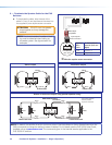
PVT RGB D Inputs
(1-4, A and B)
Power Supply
Connector
RGB
Output
Video
Output
Speaker
Output
Aux Audio
Input
MLC Control
Port
VoiceLift
Receiver Port
Lineout
Output
Volume/Mute
Control Port
Paging Sensor
Port
2A RGB
1A RGB
1B RGB
2B RGB
4A RGB
3A RGB
3B RGB
3 VIDEO
4B RGB
4 VIDEO
PVT CV D Inputs
(3 and 4)
4-Port 10/100
Ethernet Switch
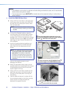
PVS 305SA IP PoleVault Switcher
Rear View
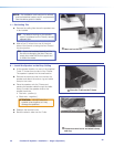
PMK Covers (2)
Base Plate
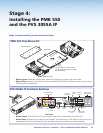
To open, remove 4 cover screws
(10-32, button head, hex) and slide
the covers away.
PMK 550 Pole Mount Kit
• Where it goes: Attaches to slotted pipe, above the projector and close to the drop ceiling.
• What it does: Supports and hides from view the installed PVS 305SA IP switcher, power supply, and any
installed optional accessories.
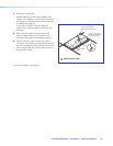
• Where it goes: PVS 305SA IP and power supply install onto the base plate of the PMK 550.
• What it does: Receives input video and audio signals, and pass through LAN data from AV source input
wall plates. Outputs and switches the video and audio signals to projector and ceiling speakers.
L R
L R
L R
AUX AUDIO
INPUT 5
LINE OUT
VOICELIFT
RECEIVER
PAGING
SENSOR
DO NOT
GROUND
OR SHORT
SPEAKER
OUTPUTS
1B RGB
1A RGB
2B RGB
2A RGB
3B RGB
/VIDEO
4B RGB
/VIDEO
3A RGB
4A RGB
I
N
P
U
T
S
RS-232 MLC/IR
2/4/8
Ohms
CLASS 2 WIRING
AMPLIFIED AUDIO OUT
VOL/MUTE
Tx Rx IR 12V
10V 50mA
POWER
US
LISTED
17TT
AUDIO/VIDEO
APPARATUS
®
RGB
VIDEO
OUTPUTS
CONTROL
N15779
12V
5A MAX
LAN 3
LAN 4
LAN 1
LAN 2
Mounting Plate
PoleVault IP Systems • Installation — Stage 4 (PMK 550 and PVS 305SA IP) 33


