


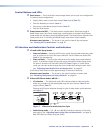
NOTES: • The length of exposed wires is critical. The ideal length is 3/16 inch (5 mm).
• If the stripped section of wire is longer than 3/16 inch, the exposed
wires may touch, causing a short circuit.
• If the stripped section of wire is shorter than 3/16 inch, wires can be
easily pulled out even if tightly fastened by the captive screws.
• Figure 4 on the preceding page identifies the tip, ring, and sleeve. A
mono audio connector consists of the tip and sleeve. A stereo audio
connector consists of the tip, ring and sleeve. If you are wiring a captive
screw connector from an existing unbalanced audio cable, the white
insulated wire is typically the left channel (tip) and the red insulated wire
is typically the right channel (sleeve). There is no reliable standard for
existing balanced audio cables.
The audio level for each input can be individually set, via the front panel or RS-232,
to ensure that the level on the output does not vary from input to input. See the
“Operation” section and the “Remote Operation” section.
By default, the audio follows the video switch. Audio breakaway, which is commanded
via the front panel, via RS-232 control using SIS commands or the Windows-based
control program, or via optional IR 501 control, allows you to select from any one of the
audio input sources. See the “Operation” section, the “Remote Operation” section,
and the IR 501 Small Matrix IR Remote Control User Guide.
Remote Connection
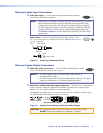
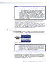
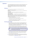
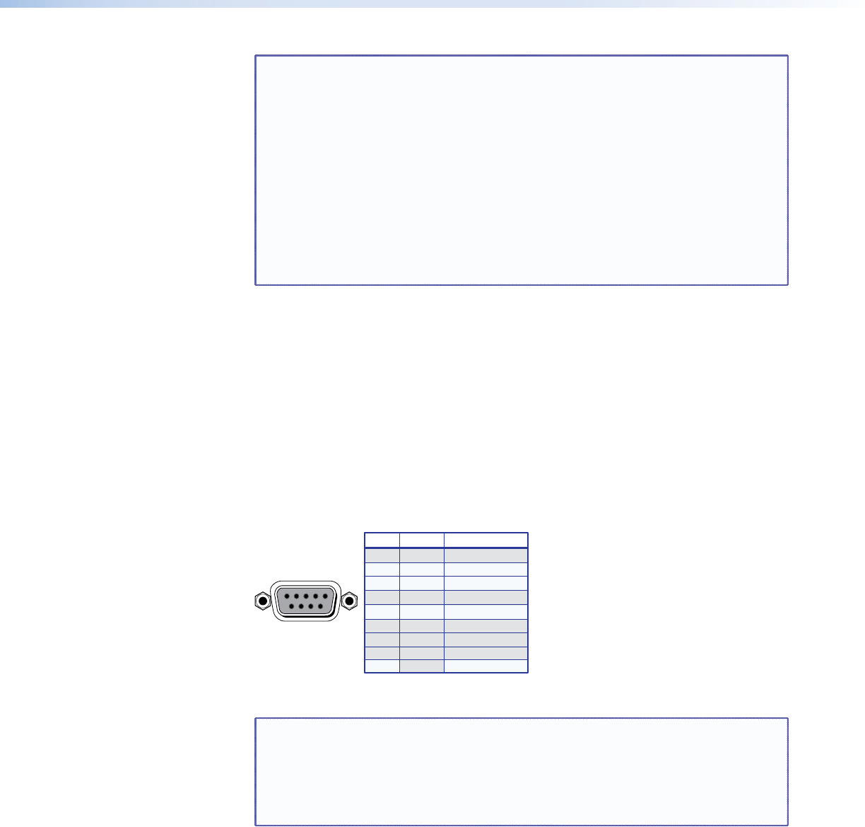
d RS-232 connector — Connect a host device, such as a computer or control system, to
the switcher via this 9-pin D connector (figure 5) for remote control of the switcher.
Pin RS-232 Function
2TX Transmit data (-)
3RX Receive data (+)
4—Not used
5 Gnd Signal ground
6—Not used
Not used
Not used
7—
8—
—
51
96
Female
Hardwired IR9
1—Not used
Figure 5. RS-232 Port Pin Assignment
NOTE: The cable used to connect the RS-232 port to a computer or control
system may need to be modified by removing pins or cutting wires. If you
encounter problems while operating under RS-232 control (the switcher
may hang up), pins 1, 4, 6, 7, and 8 may need to be disconnected. Either
cut the wire to pins 1, 4, and 6 through 8 in a hard-shelled connector or
remove pins 1, 4, and 6 through 8 from a molded plug.
See the “Remote Operation” section for definitions of the SIS commands and details
on how to install and use the control software.
Using the hardwired IR input on pin 9, you can use a control system with IR-learning
capabilities to operate the switcher just as if you were using an IR 501 remote control.
The control system must first “learn” the IR command from an IR 501, after which it
sends the same commands to the MVX via pin 9.
MVX 44 / 48 / 84 / 88 VGA Matrix Switchers • Introduction 6