Operation
This section describes the front panel operation of the MVX VGA Matrix Switcher, including:
• Front Panel Controls and Indicators
• Operations
• Optimizing the Audio
• Troubleshooting
• Worksheets
Front Panel Controls and Indicators
The number of input and output buttons and LEDs that each MVX Series VGA matrix
switcher provides varies with the number of inputs and outputs.
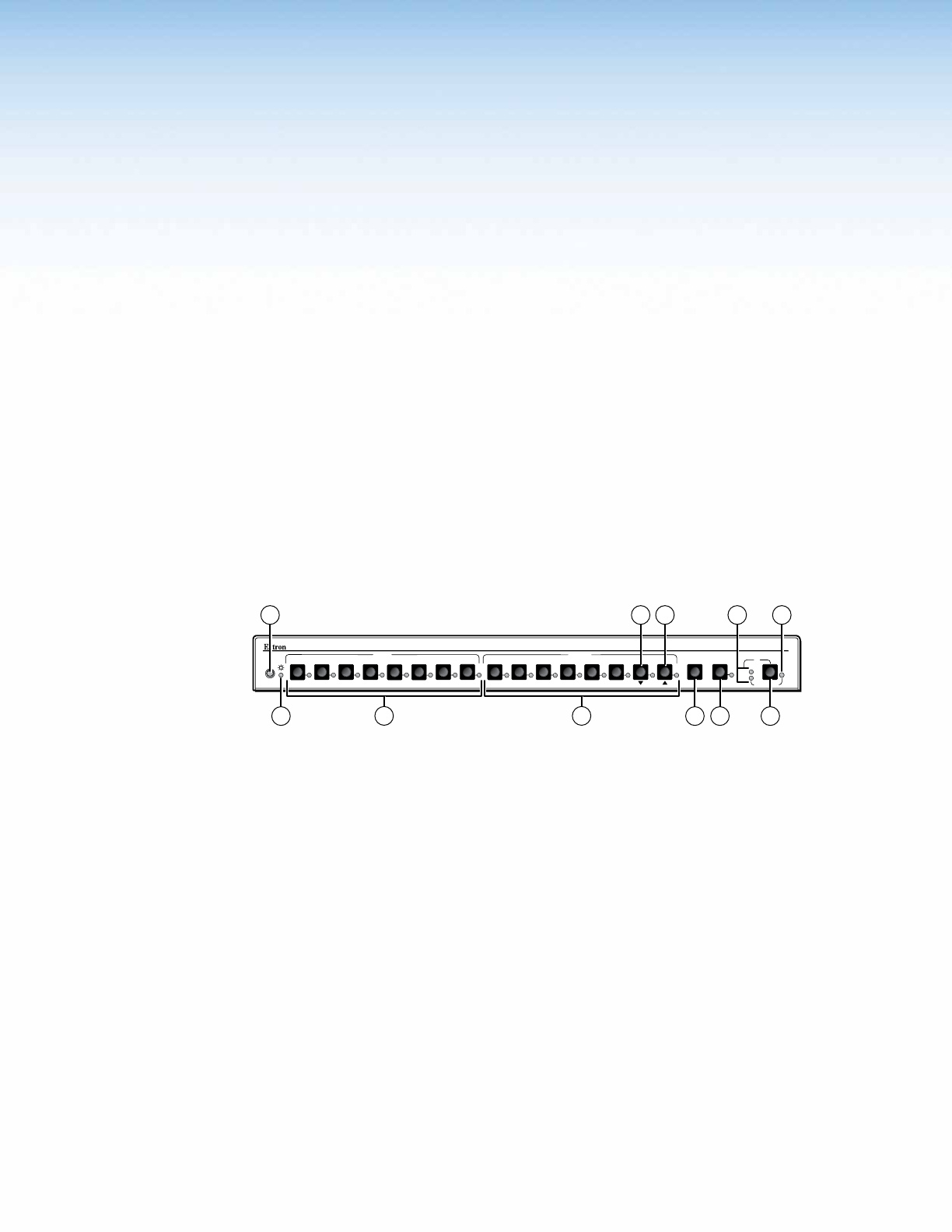
Figure 6 shows the front panel of an 8-input, 8-output video and audio switcher. Other
switcher models have fewer input and/or output buttons to accommodate the different
matrix sizes that they provide.
Many of the buttons and LEDs on figure 6 have dual functions.
MVX SERIES
VGA/AUDIO MATRIX SWITCHER
I/O
AUD
AUDIO SETUP
PRESET
VID
IR
+dB
-dB
ENTER
2
7
6
5
2 4
1
INPUTS
OUTPUTS
8
3
1
8
6
5
4
3
7
2 6 75
3 4
1 10 911 8
Figure 6. MVX 88 VGA A Front Panel
MVX 44 / 48 / 84 / 88 VGA Matrix Switchers • Operation 8


