


CIA111 and CIA114 • Installation and Operation
Installation, cont’d
2-8
CIA111 and CIA114 • Installation and Operation
2-9
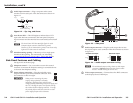
When the image is displayed correctly
Once the system has been cabled and tested, the interface can
be installed in the wall or furniture. To mount the interface
and install optional MAAP devices (CIA111 only), see the next
section, "Mounting the Interfaces".
A
u
t
o
P
o
w
e
r
A
U
D
I
O
I
N
P
U
T
M
O
N
I
T
O
R
O
U
T
P
U
T
I
M
A
G
E
S
H
I
F
T
N
O
M
O
N
I
T
O
R
C
O
M
P
U
T
E
R
I
N
P
U
T
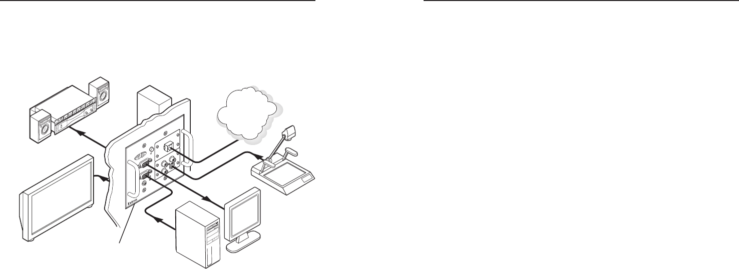
Extron
CIA111
Computer Interface
Sound System
PC
Local Monitor
Presentation Monitor
Document
Camera
LAN/WAN
Network/
Internet
C
IA11
1
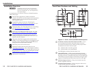
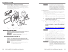
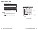
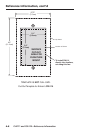
Figure 2-5 — Typical CIA111 application
Mounting the Interfaces
This section describes how to mount the interfaces. Follow the
instructions that are appropriate to your interface.
C
Installation and service must be performed by
authorized personnel only.
Mounting the CIA111 or CIA114
The CIA111 mounts to a wall or podium using a two-gang
wall box. The CIA114 mounts in a one-gang wall box. The
installation must conform to national and local electrical codes
and to the equipment’s size requirements.
N
The CIA114 requires a minimum of 3.0” H x 2.0” W x
2.5” D space inside the wall box.
C
The CIA111 and CIA114 interfaces must be
installed into Underwriters Laboratories (UL)
approved electrical wall boxes. See the following
section on UL requirements. The wall boxes are
not included with the interfaces; the installer is
responsible for obtaining and installing the boxes.
UL Requirements
The following Underwriters Laboratories (UL) requirements
listed pertain to the installation of the CIA111 and CIA114
interfaces into a wall or furniture.
1. These units are not to be used beyond their rated voltage
range.
2. These units must be installed in UL listed junction boxes.
3. These units must be installed with conduit in accordance
with the National Electrical Code.
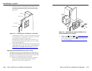
Preparing the site and installing the wall box
1. Choose an installation location that will allow cable runs
without interference. Allow enough depth for both the
wall box and the cables. You may need to install the cables
into the wall, furniture, or conduits before installing the
interface.
2. Use the appropriate template in appendix A, "Reference
Information", as a guide to measure and mark the hole in
the wall or furniture for installing the wall box.
C
The cut-out templates are not to scale and are
provided for reference only. Measure the hole
carefully before cutting.
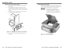
3. Check the opening size by inserting the wall box into
the opening. The box should fit easily into the opening.
Enlarge or smooth the edges of the opening, if necessary.
4. Feed cables through the wall box punch-out holes, and
secure them with cable clamps to provide strain relief.
5. Exposed cable shields (braids or foil) are potential sources
of short circuits. Trim back and/or insulate shields with
heat shrink, if needed.
W
To prevent short circuits, the outer foil shield can
be cut back to the point where the cable exits the
cable clamp. Both braided and foil shields should be
connected to an equipment ground at the other end
of the cable.