


CIA111 and CIA114 • Installation and Operation
Installation
CIA111 and CIA114 • Installation and Operation
2-2
2-3
Installation Overview
C
Installation and service must be performed by
authorized personnel only. UL Listed electrical
boxes are recommended. See "UL Requirements",
later in this chapter.
To install and set up a CIA111, CIA114, or CIA114F5 interface,
follow these steps:
1
Turn all of the equipment off. Make sure that the
computer, the interface, and the output devices (projector/
monitor, speakers) are all turned off and disconnected
from the power source.
2
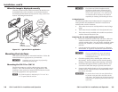
If applicable, prepare the site (see "Mounting the
Interfaces", later in this chapter, for information on your
specific installation).
3
Attach the cables. See "Front Panel Features and Cabling"
and "Side Panel Features and Cabling", later in this
chapter.
4
Set the rear panel Mode Select DIP switches. See "Side
Panel Features and Cabling" in this chapter as a guide.
5
Test the installation by connecting power cords and
turning on the projector/monitor, the audio device, the
interface, and the computer.
6
The picture should now appear, and sound should be
audible. If not, ensure that all devices are plugged in and
receiving power. Check the cabling and the DIP switch
settings, and make adjustments as needed.
7
Disconnect power from all the devices.
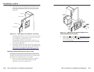
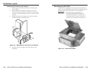
8
Mount the interface into the wall or floor box (see
"Mounting the Interfaces", later in this chapter, to address
your specific requirements). If optional MAAP devices are
being installed (CIA111 only), see "Mounting the optional
MAAP device(s)", later in this chapter.
9
Restore power to the devices.
Front Panel Features and Cabling
AUDIO INPUT
MONITOR OUTPUT
IMAGE SHIFT NO MONITOR
COMPUTER INPUT
AUDIO INPUT
MONITOR OUTPUT
IMAGE SHIFT NO MONITOR
COMPUTER INPUT
3
4
5
AUDIO
INPUT
MONITOR
OUTPUT
IMAGE
SHIFT
NO
MONITOR
COMPUTER
INPUT
2
1
6
7
3
4
5
2
1
6
2
3
1
4
5
6
CIA111 CIA114
CIA114F5
CIA111
CIA114
CIA114F5
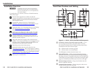
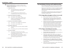
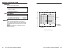
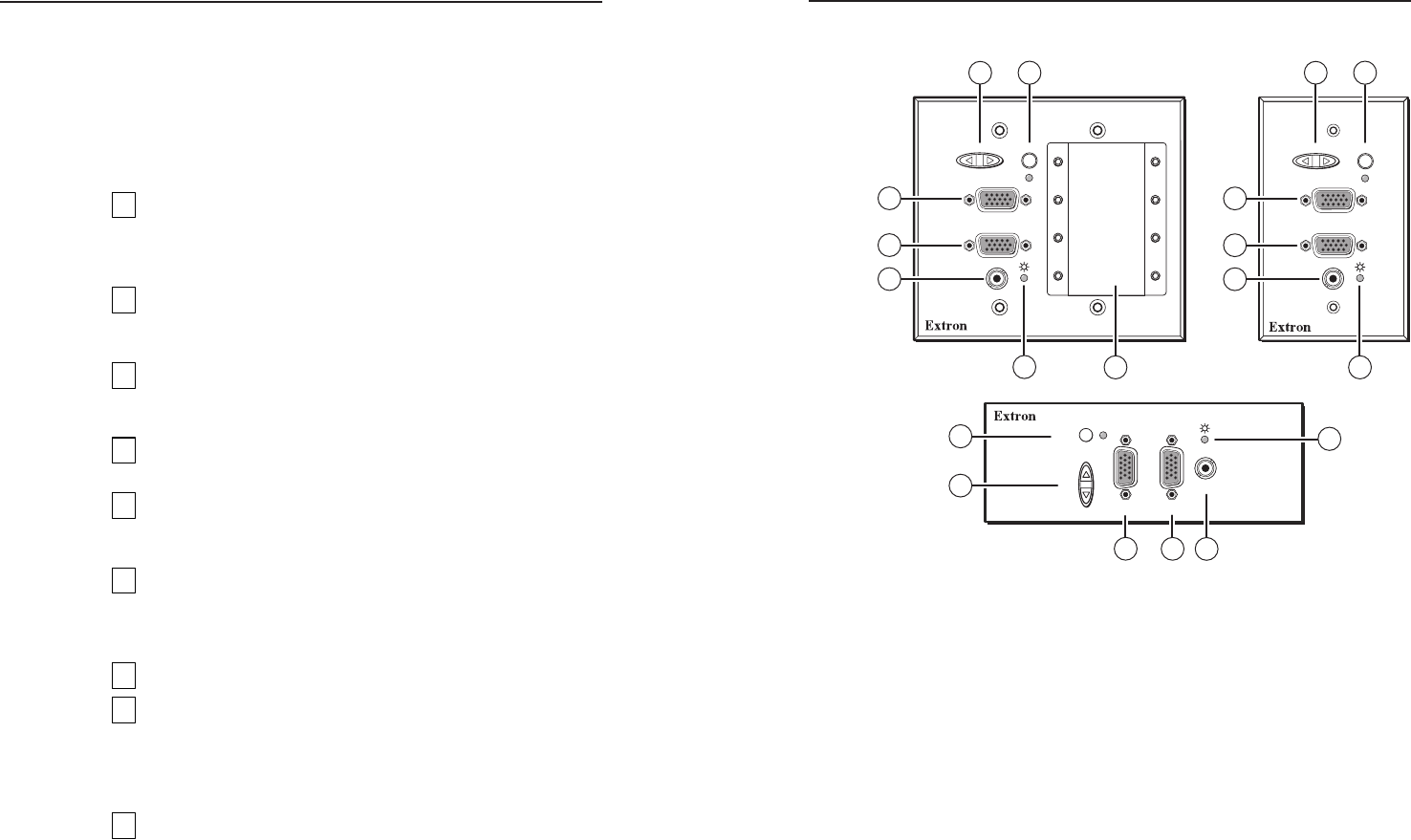
Figure 2-1 — CIA111, CIA114, and CIA114F5 front panels
a
No Monitor (monitor emulation) button and LED — If you
are not using a local monitor, press this button to turn on
the monitor emulation feature, which provides proper ID bit
termination on the local monitor output.
On — ID bits 4 and 11 are tied to ground.
Off — ID bits 4 and 11 are unterminated.
The LED lights to indicate that the feature is on.
b
Image Shift button — While viewing the displayed image,
press this rocker button to adjust the horizontal positioning of
the image on screen. Pressing the left (lower on CIA114F5) side
of the button moves the image to the left and pressing the right
(upper on CIA114F5) side of the button moves it to the right.
c
Monitor Output connector — Plug a local monitor into this
female 15-pin HD connector.
d
Computer Input connector — Plug a computer video source
into this female 15-pin HD connector.