


CIA111 and CIA114 • Installation and Operation
Installation, cont’d
2-4
CIA111 and CIA114 • Installation and Operation
2-5
e
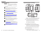
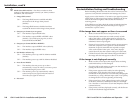
Audio Input connector — Plug a computer audio source
into this 3.5 mm stereo jack. Wire the connector as shown in
figure 2-2.
3.5 mm Audio Plug
Tip (+) Sleeve
Tip (+)
Ring (-)
Sleeve ( )
Figure 2-2 — Tip, ring, and sleeve
f
Auto Power LED — This LED lights to indicate that a VGA
input cable has been connected to the front panel Computer
Input connector and the interface has automatically turned itself
on.
N
The Auto Power LED does not light if pin 10 on the
Computer Input connector is not tied to ground.
However, if pin 10 is not tied to ground, Auto Power only
lights once a video source is connected.
g
MAAP mounting opening — Mount up to four single-space
MAAPs in this opening. For instructions, see "Mounting
optional MAAP devices (CIA111 only)", later in this chapter.
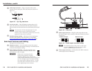
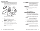
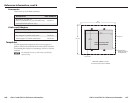
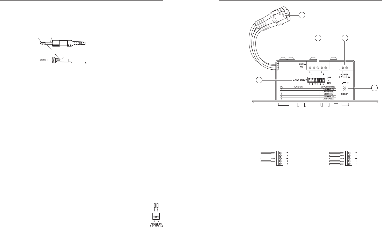
Side Panel Features and Cabling
See figure 2-3 on the next page.
a
Sharpness control — Use a screwdriver to turn this control
clockwise to increase the sharpness setting or counterclockwise
to decrease the sharpness setting.
b
Power adapter connection — Plug the included power
adapter into this 2-pole direct insertion connector. Wire
the connector as shown at right.
C
When you are connecting the power
supply, voltage polarity is extremely
important. Applying power with incorrect
voltage polarity could damage the power supply and
the CIA. Identify the power cord positive lead by
the red heat shrink wrapping around it. To verify
the polarity before connection, check the no load
power supply output with a voltmeter.
IMAGE SHIFT CONTROL
OUTPUT SYNC FORMAT (SYNC ON GREEN)
OUTPUT SYNC FORMAT (RGBHV/RGBS)
NO MONITOR AT POWER UP
AUTO POWER DISABLE/ENABLE
2
4
1
5
3
Figure 2-3 — Side panel
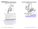
c
Audio output connector — Plug the audio output device into
this 5-pole captive screw connector. Wire the connector as shown
in figure 2-4.
Unbalanced Output
Tip
See Caution
Sleeve (s)
Tip
See Caution
Balanced Output
Tip
Ring
Sleeve (s)
Tip
Ring
L R
AUDIO
L R
AUDIO
Figure 2-4 — Audio output connector wiring
N
The unbalanced output wiring scheme on this output
connector is different from most other Extron audio
devices. Double check if you are not sure.
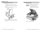
d
Video output connectors — Connect these five BNC connectors
to the display device’s RGB input.
+ –