


CIA111 and CIA114 • Installation and Operation
Installation, cont’d
2-10
CIA111 and CIA114 • Installation and Operation
2-11
2-gang
Wall Box
Au
t
o
Po
w
er
A
U
D
I
O
I
N
P
U
T
M
O
N
I
T
O
R
O
U
T
P
U
T
I
M
A
G
E
S
H
I
F
T
N
O
M
O
N
I
T
O
R
C
O
M
P
U
T
E
R
I
N
P
U
T
Extron
CIA111
Extron
MAAP
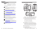
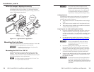
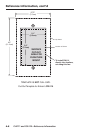
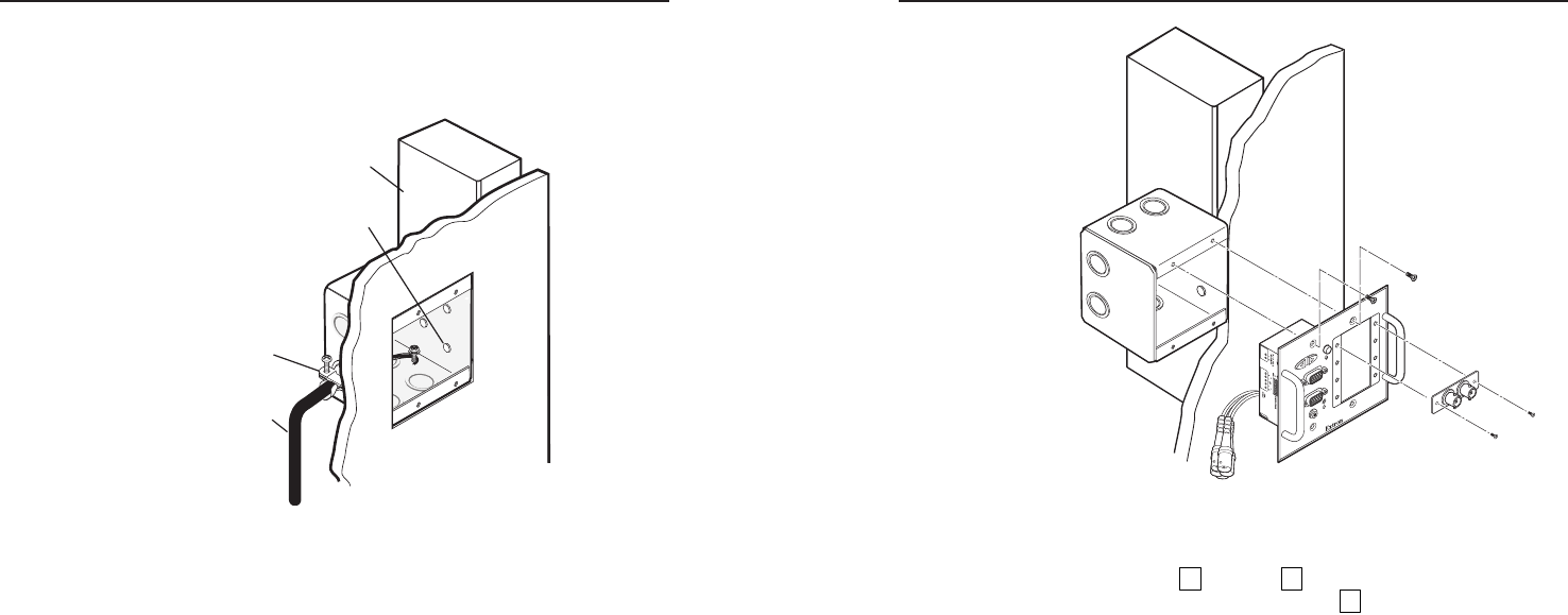
Figure 2-7 — Mounting the optional MAAP device
(standard MAAP device shown)
2. Follow steps
3
through
9
in the "Installation Overview"
section of this chapter. For step
8
(mounting the interface
to the wall box), see "Mounting the interface to the wall
box", on the next page.
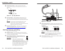
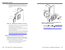
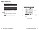
6. Insert the wall box into the opening, and attach it to the
wall stud or furniture with nails or screws, leaving the
front edge flush with the outer wall or furniture surface
(figure 2-6).
Installation Cable
Cable Clamp
Screws or Nails
Wall Stud
Figure 2-6 — Attaching the wall box to a wall stud
If attaching the wall box to wood, use four #8 or #10 screws
or 10-penny nails. A minimum of 1/2 inch (1.3 cm) of the
screw threads must penetrate the wood.
If attaching the wall box to metal studs or furniture, use
four #8 or #10 self-tapping sheet metal screws or machine
bolts with matching nuts.
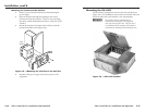
7. Set the DIP switches and cable and test the interface before
fastening the interface into the wall box. The switches and
cables will be inaccessible after installation. See "Side
Panel Features and Cabling", earlier in this chapter, for
more information.
Mounting optional MAAP devices (CIA111 only)
The interface and any optional MAAPs must be cabled before
the interface is installed in a wall or furniture. The hex screws
needed to attach the MAAPs to the interface are provided with
the MAAPs, so no additional screws are needed.
1. Before any cables are attached to the front of an MAAP
device, secure the MAAP to the faceplate with the
provided 3/32" hex screws (figure 2-7).