


CIA111 and CIA114 • Installation and Operation
Installation, cont’d
2-14
CIA111 and CIA114 Computer Video Interface
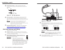
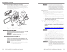
Preparing the site and cables
1. Choose a location that allows cable runs without
interference. Allow enough depth for both the floor box
and the cables. You need to run the conduit (if required by
local code) and cables under the floor before installing the
interface.
2. Install the floor box in accordance with the documentation
that accompanied the box.
3. Feed cables through the floor box punch-out holes, and
secure them with cable clamps to provide strain relief.
4. Exposed cable shields (braids or foil) are potential sources
of short circuits. Trim back and/or insulate shields with
heat shrink.
C
To prevent short circuits, the outer foil shield can
be cut back to the point where the cable exits the
cable clamp. Both braided and foil shields should be
connected to an equipment ground at the other end
of the cable.
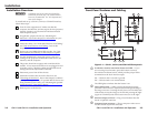
5. Set the DIP switches and cable and test the interface before
securing the device into the floor box. The switches and
cables will be inaccessible after installation.
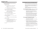
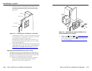
Mounting the interface to the floor box
1. Disconnect the power supply to remove power from the
interface.
2. If the floor box is installed, remove it’s top panel and trim
frame.
3. Place the interface through the opening in the floor and
into the floor box. Take care not to damage the cables,
which lie behind the interface in the bottom of the box.
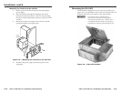
4. Attach the interface to the floor box by hooking the two
locking tabs on the bottom of the interface’s faceplate into
the slots on the bottom of the box. Secure the faceplate
to the top of the floor box with the included 1/2" Phillips
screws.
5. Install the floor box’s top panel and trim frame.
6. Reconnect the power supply.
A
Appendix A
Reference Information
Specifications
Part Numbers
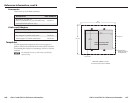
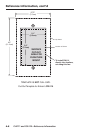
Templates