


Installation, cont’d
DVS 100 and DVS 150 Installation2-2
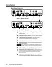
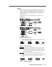
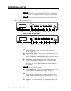
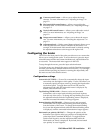
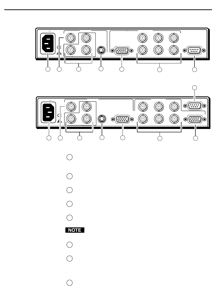
Rear Panel Features
Figure 1 — DVS 100 rear panel
Figure 2 — DVS 150 rear panel
1
AC power connector — Standard AC power connector attaches
the scaler to any power source from 100VAC to 240VAC, operating
at 50 Hz or 60 Hz.
2
Composite video input connector — One BNC female connector
for composite video input.
3
Component video input connectors — Three BNC female
connectors for component (R-Y, B-Y, Y) video input.
4
S-video input connector — One 4-pin mini-DIN female connector
for S-video input.
5
RGB output connector — One 15-pin HD female RGB connector
for the output projector.
You can install and run two output devices simultaneously, one
using BNC connectors, and the other using the RGB connector.
6
Output connectors — BNC female connectors for RGsB (sync on
green), RGBS (composite sync), or RGBHV output.
7
RS-232/contact closure remote connector — One 9-pin D female
connector that allows you to attach a computer or another device,
such as a keypad or other contact closure device, for remote
control of the scaler.
8
RGB pass-thru connector (DVS 150 only) — One 15-pin HD
female RGB connector for input. The signal from the input device
is passed through to the output connectors without being scaled.
Installation
INPUTS
R-Y
50/60 Hz
100-240V 0.3A
1
2
3
Y
B-Y
H
R
V
G
S
B
VIDEO
REMOTE
RGB
OUTPUTS
S-VIDEO
1
2
3
4
5
6
7
INPUTS
R-Y
50/60 Hz
1
2
34
Y
B-Y
H
R
V
G
S
B
VIDEO
REMOTE
RGB
RGB
S-VIDEO
OUTPUTS
1
2
3
4
6
7
5
8
100-240V 0.3A