


2-5DVS 100 and DVS 150 Installation
Cabling
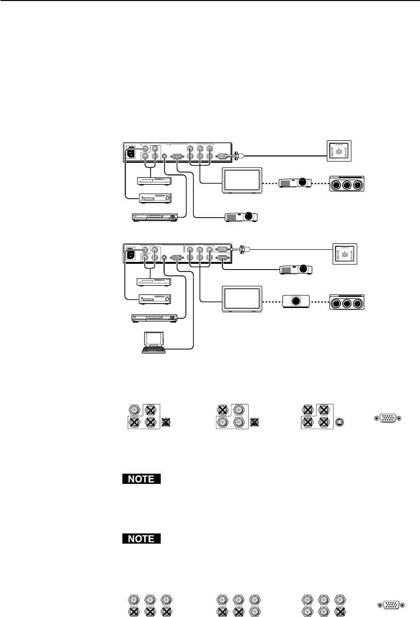
The scaler can connect to input devices that produce composite video,
S-video, or component video, and to output devices, such as LCD
projectors, DLP displays, or plasma displays. The DVS 150 can also
connect to input devices that produce RGB video via the RGB pass-
through connector.
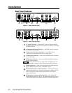
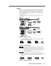
To cable the scaler, complete the following steps. Use figure 5 as a
general guide.
Figure 5 — Cabling the scaler
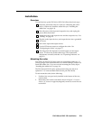
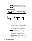
1. Attach the input device (or devices) to the scaler. Figure 6 shows
each of the connection options.
Figure 6 — Input connections
You can attach up to three input devices, one each of composite
video, S-video, and component video. You can also connect an
RGB input device, for pass-through to the output, to the DVS 150.
You can select among the input sources via the input selection
switch on the front panel.
If there is no video input, the LCD displays “No Source”.
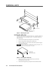
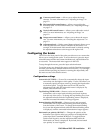
2. Use BNC connectors or a 15-pin HD connector to connect the scaler
to the output device. Figure 7 shows each of the connection
options.
Figure 7 — Output connections
INPUTS
R-Y
50/60 Hz
100-240 VAC .3A MAX
1
2
34
Y
B-Y
H
R
V
G
S
B
VIDEO
REMOTE
RGB
RGB
PASS-THRU
S-VIDEO
OUTPUTS
RS-232 Control
RS-232 Control
INPUTS
R-Y
50/60 Hz
100-240V 0.1A
1
2
3
Y
B-Y
H
R
V
G
S
B
VID
REMOTE
RGB OUT
OUTPUTS
S-VIDEO
DVS 150
DVS 100
INPUT
OUTPUT
INPUT
OUTPUT
or or
CRT ProjectorLCD Projector
DLP Projector
HDTV Plasma
or or
CRT ProjectorDLP Projector
DLP Projector
HDTV Plasma
Laptop
Computer
DVD Player
DSS Receiver
DVD Player
DSS Receiver
Laserdisc Player
Laserdisc Player
Composite Video
(Input 1)
Component Video
(Input 2)
S-video
(Input 3)
RGB
Pass-Thru
(Input 4; DVS 150 only)
R-Y
1
2
3
Y
B-Y
VID
R-Y
1
2
3
Y
B-Y
VID
R-Y
1
2
3
Y
B-Y
VID
RGsB RGBS RGBHV
RGB Output
H
R
V
G
S
B
H
R
V
G
S
B
H
R
V
G
S
B