


4-3
DVS 100 and DVS 150 Serial Communication
RS-232 Programmer’s Guide
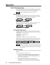
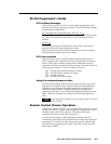
DVS initiated messages
When a local event occurs, such as a front panel operation, the scaler
responds by sending a message to the host. The DVS-initiated messages
are listed below (underlined).
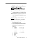
(C) Copyright 1999, Extron Electronics, DVS xxx, V
x.x
The copyright message is initiated by the scaler when it is first powered
on. DVS xxx is the scaler model, and Vx.xx is the firmware version
number.
Reconfig
The Reconfig message is initiated by the scaler when a new input is
selected or when any image adjustment is made.
The scaler does not expect a response from the host, but, for example,
the host program might request a new status.
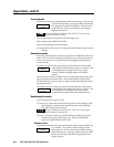
DVS error response
When the scaler receives an SIS command and determines that it is
valid, it performs the command and sends a response back to the host
device. If the scaler is unable to perform the command because the
command is invalid or contains invalid parameters, the scaler returns an
error response to the host. The error response codes are:
E01 — Invalid input channel number (too large)
E09 — Invalid function number (too large)
E10 — Invalid command
E13 — Invalid value (out of range)
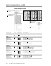
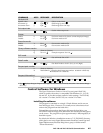
Using the command/response table
The command/response table is shown on the next page. Lower case
characters are acceptable in the command field only where indicated.
Symbols are used throughout the table to represent variables in the
command/response fields. Symbol definitions are shown at the
beginning of the table, as is an ASCII-to-hexadecimal (HEX) conversion
table. Command and response examples are shown throughout the
table.
Screen adjustment commands are not available if input 4 is selected
(DVS 150 only).
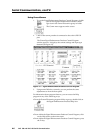
Remote Contact Closure Operation
The RS-232 connector provides a way to control the scaler from a remote
contact closure device. This is made possible by using pins that are not
normally used by the RS-232 interface. The contact closure pin
assignments are shown in the table on page 4-2.
To select a different input number through the RS-232 connector,
momentarily short the pin for the desired input number (#) to the signal
ground (pin 5). To force one of the inputs to be selected continuously,
leave the short to signal ground in place. This will override any front
panel input selection.