


Serial Communication, cont’d
DVS 100 and DVS 150 Serial Communication
4-2
Serial Communication
RS-232
Control Cable
RS-232
Control Cable
DVS 100
DVS 150
Computer Control
H
R
V
G
S
B
REMOTE
OUTPUTS
H
R
V
G
S
B
REMOTE
RGB
OUTPUTS
Computer Control
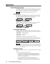
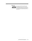
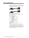
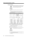
The scaler’s RS-232 connector can be connected to the serial port output
of a host device such as a computer or control system. This connection
makes software control of the scaler possible. Figure 14 shows a scaler
RS-232 connection to a host serial port connector.
Figure 14 — Scaler RS-232 to host connection
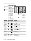
The RS-232 connector on the scaler is a 9-pin D female connector with
the following pin assignments:
Pin Description
1 Input 1 select*
2 Transmit data
3 Receive data
4 Input 2 select*
5 Signal ground
6 Input 3 select*
7 Input 4 select* (DVS 150 only)
8 Not used
9 Not used
* Used for remote contact
closure control
The protocol is 9600 baud, 8-bit, 1 stop bit, no parity, and no flow
control.
The DVS 100 or DVS 150 scaler accepts SIS™ (Simple Instruction Set™)
commands through the RS-232 port. SIS commands consist of one or
more characters per command field. They do not require any special
characters to begin or end the command character sequence. Each scaler
response to an SIS command ends with a carriage return and a line feed
(CR/LF =
), which signals the end of the response character string. (A
string is one or more characters.)