


e
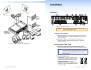
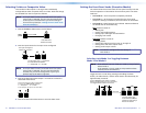
Composite video outputs (Output 7 and Output 8) —
Connect composite video displays to these female BNC connectors.
NOTE: If the input tied to Output 7 or Output 8 is S-video,
the switcher encodes the input to composite video.
If the tied input is composite video, the switcher
passes it through to the output with no processing.
f
S-video outputs (Output 9 and Output 10) —
Connect S-video displays to these female BNC connectors.
NOTE: If the input tied to Output 9 or Output 10 is composite
video, the switcher decodes the input to S-video.
If the tied input is S-video, the switcher passes it
through to the output with no processing.
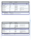
g
Pass-through outputs
12
Y/VID
S-video Composite
video
C
11
(Output 11 and Output 12) —
Connect S-video or composite video displays to
these female BNC connectors. Connect S-video
Y and C or composite video as shown at right.
NOTE: The switcher passes the tied input to these outputs
with no signal processing; an S-video input is output
as S-video, a composite video input is output as
composite video.
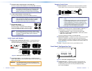
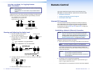
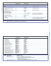
Audio Inputs and Outputs
h
Balanced and unbalanced audio inputs — Connect balanced or
unbalanced stereo audio inputs to these 5-pole captive screw
connectors (see figure 3 for wiring).
LR
Unbalanced Input
Balanced Input
Ring
Sleeve (s)
Tip
Sleeve
Tip
Sleeve
Tip
Tip
Ring
Do not tin the wires!
Balanced Output
LR
Ring
Tip
Sleeve(s)
Tip
Ring
Unbalanced Output
Sleeve(s)
Tip
Tip
NO GROUND
NO GROUND
Figure 3. Audio Input Connector Wiring
i
Local audio outputs — Connect balanced or unbalanced stereo
audio output devices to these 5-pole captive screw connectors (see
figure 3 for wiring).
CAUTION: For unbalanced audio, connect the sleeves to the
ground contact. DO NOT connect the sleeves to the
negative (-) contacts).
Remote Control Ports
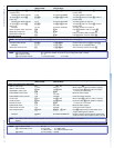
j
RS-232 connectors — Connect one or two host devices to these
3-pole captive screw connectors for serial RS-232 (see figure 4).
Rx
Tx
PC
Ground ( )
Receive (Rx)
Transmit (Tx)
Rx
Tx
Bidirectional
Figure 4. RS-232 Connector
NOTES: • ThetworearpanelportsarehardwiredforRS-232
only.
• The RS-232 Secondary port is active only if the front
panel Configuration port is not in use. If a front
panel configuration connection is made, the rear
panel RS-232 Secondary port becomes inactive and
the front panel Configuration port is active.
• See figure 3 for wire stripping information.
k
LAN port — If desired, connect a network WAN or LAN hub, a
control system, or computer to the Ethernet RJ-45 port.
• Network connection — Wire as a patch (straight) cable.
• Computer or control system connection — Wire the interface
cable as a crossover cable.
The factory default IP address is 192.168.254.254.
l
Reset button and LED — Initiates four levels of reset of the matrix
switcher. For different reset levels, press and hold the button
while the switcher is running or while you power up the switcher.
See the MPX 866 A User Guide, available on the Extron DVD or at
www.extron.com.
m
Power — Plug the switcher into a grounded AC source.
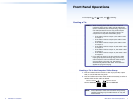
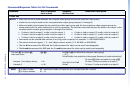
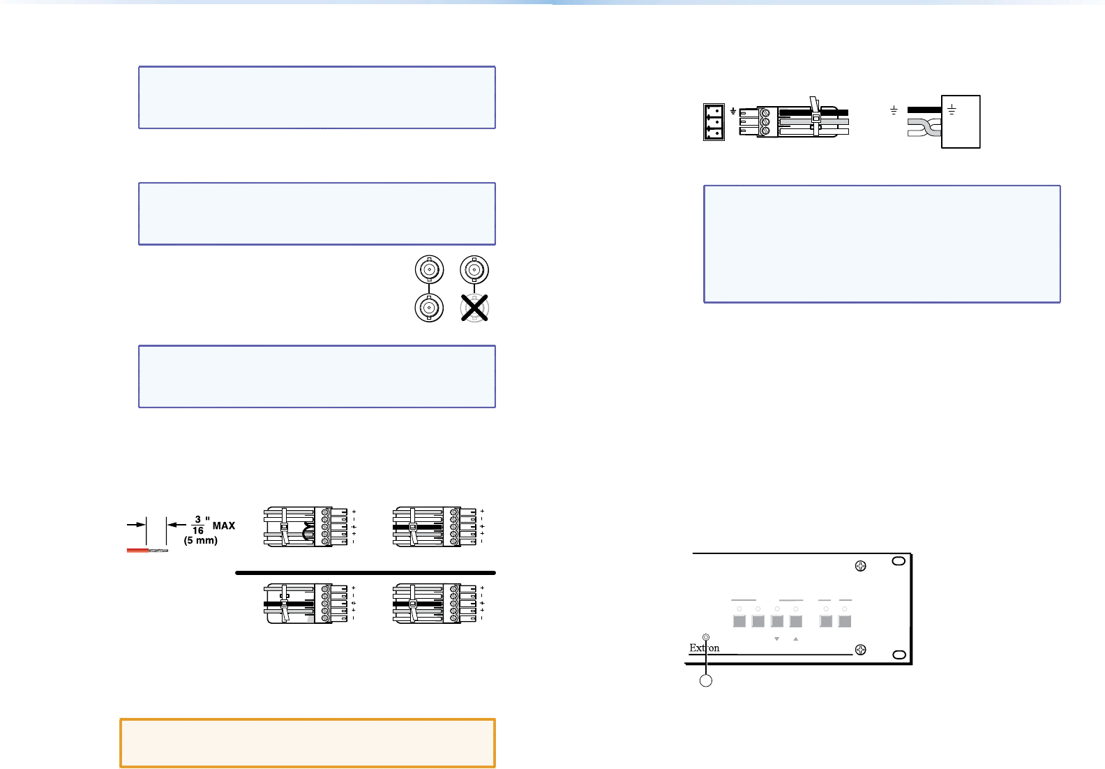
Front Panel Configuration Port
AUDIO
VIDEO
I/O
CONTROL
ENTER PRESET
VIEW
ESC
PRESENTATION MATRIX SWITCHER
MPX 866 A
CONFIG
14
Figure 5. Front Panel Configuration Port
n
Configuration port — If desired, connect a control system or
computer to the front panel Configuration (RS-232) port. Use
an optional 9-pin D to 2.5 mm mini jack TRS RS-232 cable,
part number 70-335-01.
4 MPX 866 A • Installation 5MPX 866 A • Installation