


Installation and Operation
QSD 204 • Installation and Operation2-4
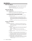
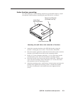
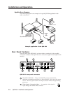
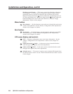
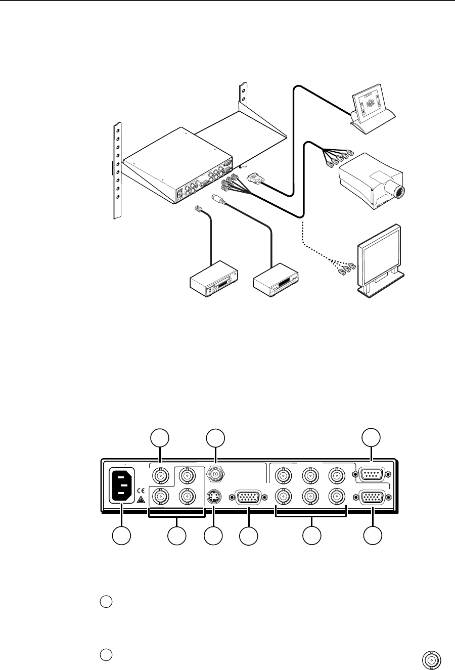
Application diagram
The following diagram is an example of a typical QSD 204 application with
cable connections.
Example application of the QSD 204
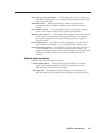
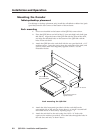
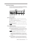
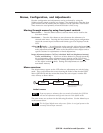
Rear Panel Features
The rear panel of the QSD 204 D, as shown below, contains all of the possible
connectors available on the QSD 204 series of decoders (QSD 204 and QSD 204 D
models).
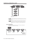
QSD 204 D rear panel connectors
1
AC power connector — Plug a standard IEC power cord into this
connector to connect the decoder to a 100 to 240VAC, 50 Hz or 60 Hz power
source. The front panel control and input selection LEDs will light during
power-up.
2
Video input 1: Composite video — A composite video signal is
input through the female BNC connector.
INPUTS
R-Y
50/60 Hz
1
2
34
Y
/VID
B-Y
/C
H
R
/R-Y
V
G
/Y
S
B
/B-Y
VIDEO
REMOTE
RGB/R-Y,Y,B-Y
RGBS/
RGBcvS
S-VIDEO
SDI
OUTPUTS
100-240V 0.3A
1
2
3
5
4
6
8
9
7
1
VIDEO
RS-232 Control
VCR
IN
PU
TS
R-Y
1
2
3
Y
B-Y
/C
SDI
H
R
V
G
S
B
VIDEO
REMOTE
RGB/R-Y,Y,B-Y
RGB
PASS-THRU/
RGBcS
O
UTPUTS
Extron
QSD 204
Quad Standard Decoder
Projector
RGBHV
or
RGB
DVD Player
Plasma