


3-3QSD 204 • Serial Communication
Using the command/response tables
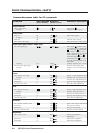
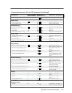
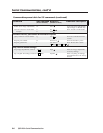
The command/response tables on the next page list valid command ASCII codes,
the decoder’s responses to the host, and a description of the command’s function
or the results of executing the command. Upper and lower case characters may be
used interchangeably in the command field.
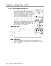
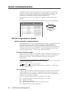
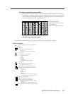
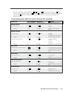
The ASCII to HEX
conversion table at left is for
use with the
command/response tables.
ASCII to Hex conversion table
ASCII to HEX Conversion Table
•
The command/response tables use symbols (defined below) to represent variables.
Symbol definitions
= CR/LF (carriage return/line feed) (hex 0D 0A)
• = Space
Esc
= Escape key
X1
= Specific input number (0 through 4)
0 = no input
1 = input 1, 2 = input 2, and so forth
X2
= 0 = off, 1 = on
X4
= Video signal type (1 through 7)
1 = composite video
2 = YC
3 = YUV
5 = RGBS
6 = RGBcvS
7 = SDI (serial digital interface)
X5
= Input (1 to 4)
X8
= Controller firmware version (listed to
two decimal places e.g.: x.xx)
X10
= Picture adjustment range (0 through 255)
X12
= Detected input signal standard (0 through 4)
0 = none
1 = NTSC 3.58
2 = PAL
3 = NTSC 4.43
4 = SECAM
– = not applicable (occurs when the input is
set for RGB, YUV, or progressive YUV)
X13
= Detail level (0 through 63)
X14
= Adjustment range (0 through 127)
X16
= Executive mode status (0 through 2)
0 = disabled (executive mode off, normal
mode on)
1 = enabled, image adjustments are locked
X17
= Blanking adjustment range (0 through 127 lines)