


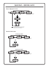
Quick Start — QSD 204
Installation
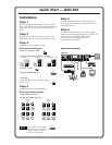
Step 1
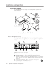
Refer to the application example at the end of this
page. Turn off power to the decoder and input and
output devices, and remove power cords from
them.
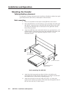
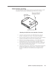
Step 2
Install the four rubber feet on the bottom of the
QSD 204 decoder, or mount the decoder in a rack.
Step 3
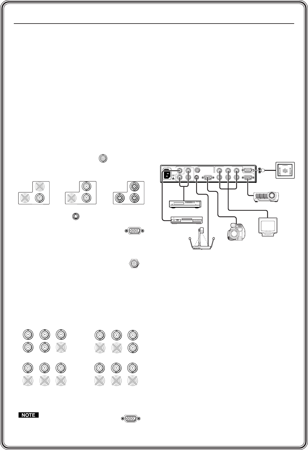
Attach input devices to the decoder.
Rear panel video inputs
Input 1: Composite video
Input 2: Composite/S-video/Component
Input 3: S-video
Input 4: RGBS/RGBcvS
SDI input
Attach an SDI source to this BNC (204 D
model only).
Step 4
Attach output devices to the decoder.
Rear panel video outputs
Output BNC connectors
Output 15-pin HD connector
You can connect both outputs
simultaneously to two different
displays. The sync format is
the same for both outputs.
Video Camera
DVD Player
INPUTS
R-Y
50/60 Hz
1
2
34
Y
/VID
B-Y
/C
H
R
/R-Y
V
G
/Y
S
B
/B-Y
VIDEO
REMOTE
RGB/R-Y,Y,B-Y
RGBS/
RGBcvs
S-VIDEO
SDI
OUTPUTS
100-240V 0.3A
QSD 204
VCR
Document Camera
RS-232 Control
Monitor
LCD Projector
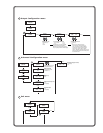
Application example
1
VIDEO
R-Y
2
Y
/VID
B-Y
/C
R-Y
2
Y
/VID
B-Y
/C
Composite Video
Component Video (R-Y, Y, B-Y)
S-video (Y/C)
R-Y
2
Y
/VID
B-Y
/C
3
S-VIDEO
4
RGBS/
RGBcvS
SDI
H
R
/R-Y
V
G
/Y
S
B
/B-Y
OUTPUTS
H
R
/R-Y
V
G
/Y
S
B
/B-Y
OUTPUTS
H
R
/R-Y
V
G
/Y
S
B
/B-Y
OUTPUTS
H
R
/R-Y
V
G
/Y
S
B
/B-Y
OUTPUTS
Component Video (R-Y, Y, B-Y)
RGBHV
RGBS
RGsB
Step 5
Plug the QSD 204, and input and output devices
into a grounded AC source, and turn on the input
and output devices.
Step 6
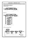
Use the LCD menu screens (see the next page) or
RS-232 programming to configure the decoder. See
chapter two for installation and operation
procedures, and see chapter three for
programming information.
RGB/R-Y,Y,B-Y