


SVS 100 Installation
2-3
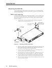
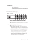
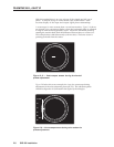
Rack mounting
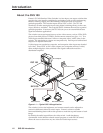
Rack mount the switcher as follows:
1. Attach the rack mount brackets to the switcher with eight #8 machine
screws, provided (see figure 2-1).
2. Insert the switcher into the rack, align the holes in the mounting bracket
with those of the rack.
3. Secure the switcher to the rack using the supplied machine screws.
Cabling and Rear Panel Views
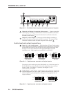
All connectors are on the rear panel (see figures 2-2, 2-3, and 2-6).
Power connection
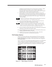
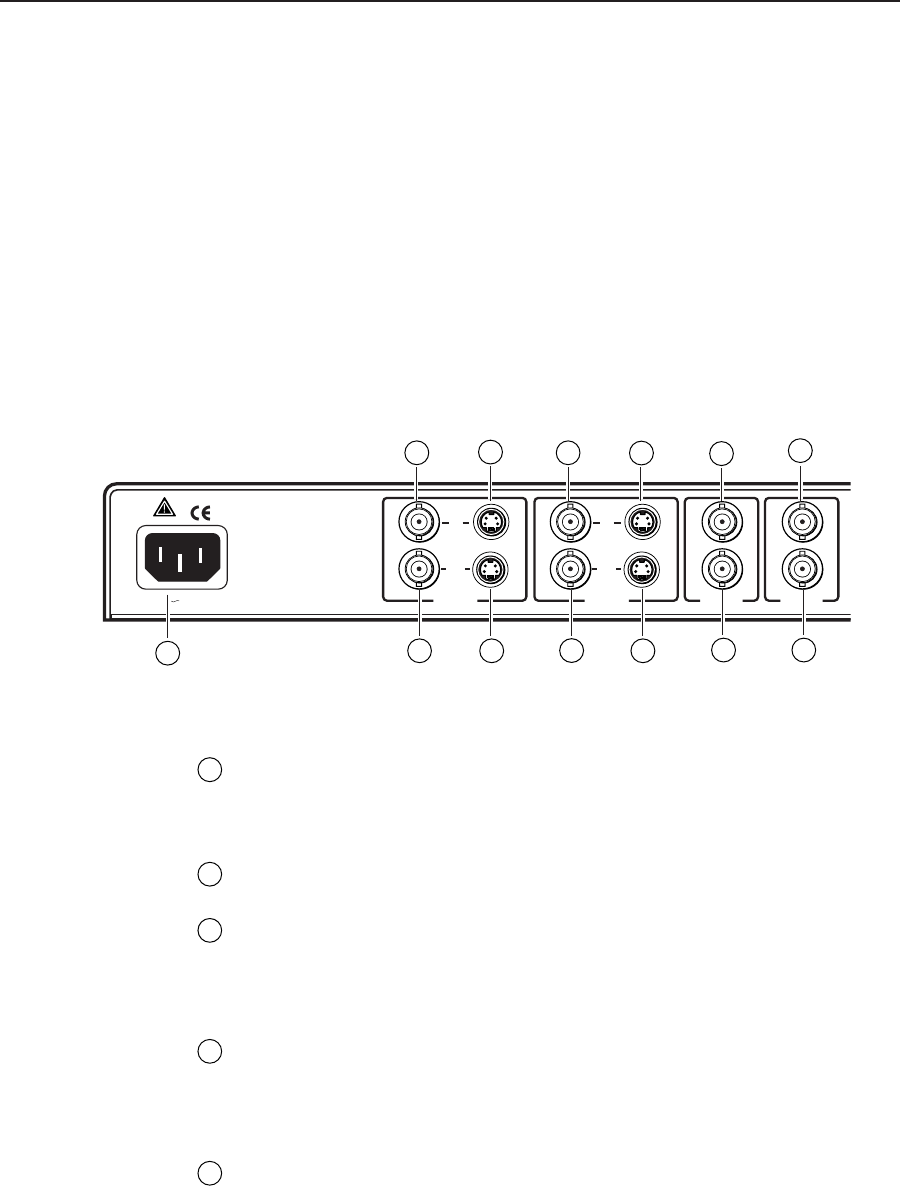
Figure 2-2 — Power, video input, and buffered video outputs
1
AC power connector — Plug a standard IEC power cord into this connector
to connect the switcher to a 100 to 240VAC, 50 Hz or 60 Hz power source.
Video input and output connections
2
Input 1, Input 2, Input 3, and Input 4, composite video inputs — Connect
composite video inputs to these BNC connectors.
3
Input 1 and Input 2, S-video inputs — Connect S-video inputs to these
4-pin mini-DIN connectors. If both composite video and S-video are
connected to Input 1 or Input 2, the switcher can autoselect the active line if
the input has been configured as “Auto”. See Advanced Menus and the Input
video type section in chapter 3. If both lines are active, S-video is selected.
4
Input 1, Input 2, Input 3, and Input 4, composite video buffered outputs —
These BNC connectors output unswitched bufferd loops of the composite
video input. The buffered output loops are always active, independent of
autoselection. See Advanced Menus and the Input video type section in
chapter 3.
5
Input 1 and Input 2, S-video buffered outputs — These 4-pin mini-DIN
connectors output unswitched buffered loops of the S-video input. The
buffered output loops are always active, independent of autoselection. See
Advanced Menus and the Input video type section in chapter 3.
100-240V 50/60 Hz 0.5A
OUT
IN
INPUT 1
OUT
IN
OUT
IN
INPUT 2 INPUT 3
OUT
IN
INPUT 4
2
2
2
3
3
4
4
4
4
5 5
1
2