


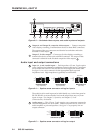
SVS 100 Installation
Installation, cont’d
2-8
0
10
20
30
40
50
60
70
80
90
100
110
120
130
140
150
160
170
180
190
200
210
220
230
240
250
260
270
280
290
300
310
320
330
340
350
+40
-40
A1
A2
A3
B1
B2
B3
0
10
20
30
40
50
60
70
80
90
100
110
120
130
140
150
160
170
180
190
200
210
220
230
240
250
260
270
280
290
300
310
320
330
340
350
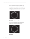
With this method there is no way to know if the signals are 180º out of
phase. A delayed sweep on a time-based scope would allow a more
accurate display of the input and output signal phase relationships.
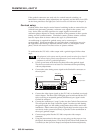
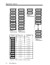
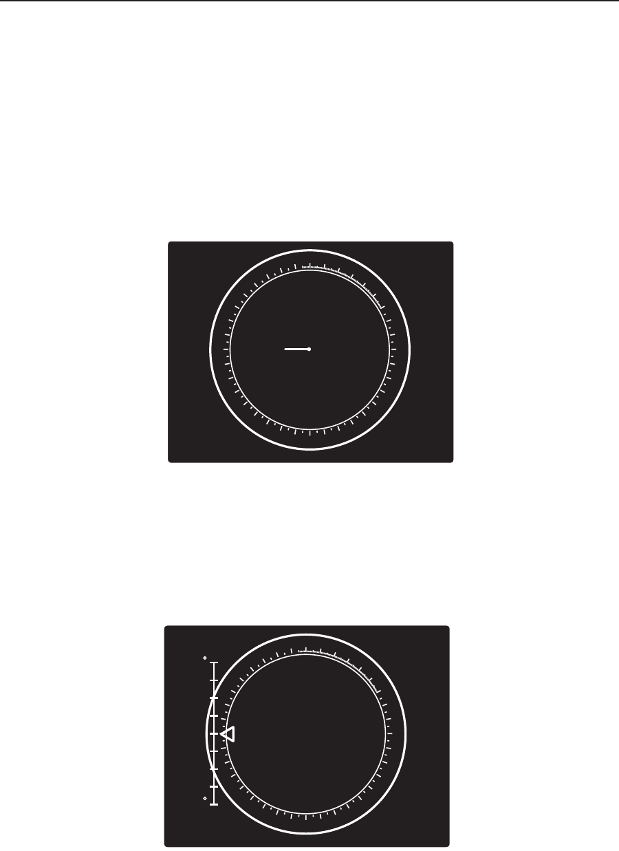
A vectorscope is more accurate than a waveform monitor. Figure 2-8 shows
an example of a vectorscope display when the horizontal phase is adjusted
to align it with the burst (genlock) vector. Adjust the horizontal phase by
rotating the encoder knob until the difference between the two vectors is 0º.
This example shows black burst only (with no color). The burst vector is
pointing to the left from the center.
Figure 2-8 — Vectorscope screen during horizontal
phase adjustment
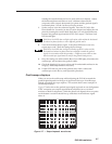
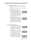
Figure 2-9 below shows an example of a view of a vectorscope during
adjustment of the color subcarrier phase (SC/H). The subcarrier phase
should be aligned to 0º (indicated in the figure by the triangle).
Figure 2-9 — Vectorscope screen during color subcarrier
phase adjustment