


©2002 Fairchild Semiconductor Corporation Application Note 7511 Rev. A1
Insulated-Gate Transistors Simplify AC-Motor
Speed Control
An IGT’s few input requirements and low On-state resistance
simplify drive circuitry and increase power efficiency in motor-
control applications. The voltage-controlled, MOSFET-like
input and transfer characteristics of the insulated-gate transis-
tor (IGT) (see EDN, September 29, 1983, pg 153 for IGT
details) simplify power-control circuitry when compared with
bipolar devices. Moreover, the IGT has an input capacitance
mirroring that of a MOSFET that has only one-third the power-
handling capability. These attributes allow you to design sim-
ple, low-power gate-drive circuits using isolated or level-shift-
ing techniques. What’s more, the drive circuit can control the
IGT’s switching times to suppress EMI, reduce oscillation and
noise, and eliminate the need for snubber networks.
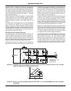
Use Optoisolation To Avoid Ground Loops
The gate-drive techniques described in the following sections
illustrate the economy and flexibility the IGT brings to power
control: economy, because you can drive the device’s gate
directly from a preceding collector, via a resistor network, for
example; flexibility, because you can choose the drive circuit’s
impedance to yield a desired turn-off time, or you can use a
switchable impedance that causes the IGT to act as a charge-
controlled device requiring less than 10 nanocoulombs of
drive charge for full turn-on.
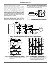
Take Some Driving Lessons
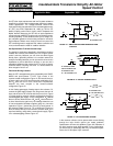
Note the IGT’s straightforward drive compatibility with CMOS,
NMOS and open-collector TTL/HTL logic circuits in the
common-emitter configuration Figure 1A. R
3
controls the turn-
off time, and the sum of R
3
and the parallel combination of R
1
and R
2
sets the turn-on time. Drive-circuit requirements,
however, are more complex in the common-collector
configuration Figure 1B.
In this floating-gate-supply floating-control drive scheme, R
1
controls the gate supply’s power loss, R
2
governs the turn-off
time, and the sum of R
1
and R
2
sets the turn-on time. Figure
1C shows another common-collector configuration employing
a bootstrapped gate supply. In this configuration, R
3
defines
the turn-off time, while the sum of R
2
and R
3
controls the turn-
on time. Note that the gate’s very low leakage allows the use
of low-consumption bootstrap supplies using very low-value
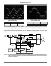
capacitors. Figure 1 shows two of an IGT’s strong points. In
the common-emitter Figure 1A, TTL or MOS-logic circuits can
drive the device directly. In the common-collector mode, you’ll
need level shifting, using either a second power supply Figure
1B or a bootstrapping scheme Figure 1C.
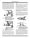
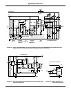
In the common-collector circuits, power-switch current flowing
through the logic circuit’s ground can create problems.
Optoisolation can solve this problem (Figure 2A.) Because of
the high common-mode dV/dt possible in this configuration,
you should use an optoisolator with very low isolation capaci-
tance; the H11AV specs 0.5pF maximum.
FIGURE 1A
.
SIMPLE DRIVING AND TRANSITION-TIME
CONTROL
FIGURE 1B. A
SECOND POWER SUPPLY
FIGURE 1C. BOOTSTRAPPING SCHEME
LOAD
V
CC
R
1
R
3
R
2
ON
OFF
15
V
CC
R
2
R
1
R
2
+
--------------------
25V
≤≤
R
3
CONTROLS t
OFF
LOAD
V
CC
CONTROL
INPUT
ON
OFF
15V
R
1
R
2
R
1
CONTROLS GATE
SUPPLY POWER LOSS
R
2
CONTROLS t
OFF
R
1
+ R
2
CONTROLS t
ON
LOAD
ON
OFF
15
V
CC
R
2
R
1
R
2
+
--------------------
25V
≤≤
R
3
CONTROLS t
OFF
R
2
+ R
3
CONTROLS t
O
N
τ
5C
I
CEO
I
GES
2I
R
++
-------------------------------------------------«
R
1
R
3
R
2
Application Note September 1993 AN-7511
/T
itle
AN
75
1)
Su
b-
ect
In
ula
ted
Ga
te
ra
n
ist
ors
im
-
lif
y
C
-
o
tor
pe
ed
on
-
rol
)
Au
tho
()
Ke
y-
or
ds
Int
er-
il
or
po-
ati
on,
em
i-
on
-
uc
tor,
va
-
anc
he
ne
rgy
at
ed,
w
itch
ng
ow
er
up
-
lie
,
ow
er