


©2002 Fairchild Semiconductor Corporation Application Note 7511 Rev. A1
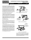
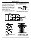
For optically isolated “relay-action” switching, it makes sense
to replace the phototransistor optocoupler with an H11L1
Schmitt-trigger optocoupler (Figure 2B).) For applications
requiring extremely high isolation, you can use an optical fiber
to provide the signal to the gate-control photodetector. These
circuit examples use a gate-discharge resistor to control the
IGT’s turn-off time. To exploit fully the IGT’s safe operating
area (SOA), this resistor allows time for the device’s minority
carriers to recombine. Furthermore, the recombination occurs
without any current crowding that could cause hot-spot forma-
tion or latch-up pnpn action. For very fast turn-off, you can use
a minimal snubber network, which allows the safe use of lower
value gate resistors and higher collector currents.
Pulse-Transformer Drive Is Cheap And Efficient
Photovoltaic couplers provide yet another means of driving the
IGT. Typically, these devices contain an array of small silicon
photovoltaic cells, illuminated by an infrared diode through a
transparent dielectric. The photovoltaic coupler provides an
isolated, controlled, remote dc supply without the need for
oscillators, rectifiers or filters. What’s more, you can drive it
directly from TTL levels, thanks to its 1.2V, 20mA input
parameters.
Available photovoltaic couplers have an output-current
capability of approximately 100µA. Combined with
approximately 100kΩ equivalent shunt impedance and the
IGT’s input capacitance, this current level yields very long
switching times. These transition times (typically ranging to 1
msec) vary with the photovoltaic coupler’s drive current and the
IGT’s Miller-effect equivalent capacitance.
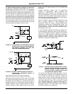
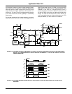
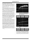
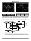
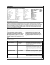
Figure 3 illustrates a typical photovoltaic-coupler drive along
with its transient response. In some applications, the
photovoltaic element can charge a storage capacitor that’s
subsequently switched with a phototransistor isolator. This
isolator technique - similar to that used in bootstrap circuits
provides rapid turn-on and turn-off while maintaining small size,
good isolation and low cost.
In common-collector applications involving high-voltage, reac-
tive-load switching, capacitive currents in the low-level logic cir-
cuits can flow through the isolation capacitance of the control
element (eg, a pulse transformer, optoisolator, piezoelectric
coupler or level-shift transistor). These currents can cause
undesirable effects in the logic circuitry, especially in high-
impedance, low-signal-level CMOS circuits.
FIGURE 3. AS ANOTHER OPTICAL-DRIVE OPTION, A PHOTO-
VOLTAIC COUPLER PROVIDES AN ISOLATED,
REMOTE DC SUPPIY TO THE IGT’S INPUT. ITS
LOW 100µA OUTPUT, HOWEVER, YIELDS LONG
IGT TURN-ON AND TURN-OFF TIMES.
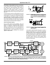
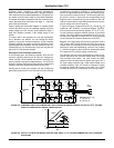
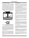
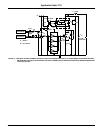
The solution? Use fiber-optic components Figure 4 to elimi-
nate the problems completely. As an added feature, this low-
cost technique provides physical separation between the
power and logic circuitry, thereby eliminating the effects of
radiated EMI and high-flux magnetic fields typically found
near power-switching circuits. You could use this method
with a bootstrap-supply circuit, although the fiber-optic sys-
tem’s reduced transmission efficiency could require a
gain/speed trade-off. The added bipolar signal transistor
minimizes the potential for compromise.
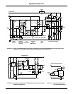
FIGURE 2A. AVOID GROUND-LOOP PROBLEMS BY USING AN
OPTOISOLATOR. THE ISOLATOR IGNORES SYS-
TEM GROUND CURRENTS AND ALSO PRO-
VIDES HIGH COMMON-MODE RANGE.
FIGURE 2B. A SCHMITT-TRIGGER OPTOISOLATOR YIELDS
“SNAP-ACTION” TRIGGERING SIMILAR TO
THAT OF A RELAY.
LOAD
V
CC
R
1
R
2
R
3
CONTROL
INPUT
C
OFF
ON
H11AV2
LOAD
V
CC
= 300V
43k
1N5061
5.6k
10µF
35V
CONTROL
INPUT
OFF
ON
H11L1
5.6k 5.6k
DIG22
IGT
ON
OFF
CONTROL
INPUT
+
-
I
OUTPUT
CURRENT
INPUT
CURRENT
012ms
Application Note 7511