


©2002 Fairchild Semiconductor Corporation Application Note 7511 Rev. A1
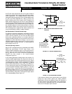
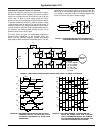
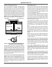
A piezoelectric coupler operationally similar to a pulse-train
drive transformer, but potentially less costly in high volume is
a small, efficient device with isolation capability ranging to
4kV. What’s more, unlike optocouplers, they require no
auxiliary power supply. The piezo element is a ceramic
component in which electrical energy is converted to
mechanical energy, transmitted as an acoustic wave, and
then reconverted to electrical energy at the output terminals
Figure 5A.
The piezo element’s maximum coupling efficiency occurs at
its resonant frequency, so the control oscillator must operate
at that frequency. For example, the PZT61343 piezo coupler
in Figure 5B’s driver circuit requires a 108kHz, ±1%-accurate
astable multivibrator to maximize mechanical oscillations in
the ceramic material. This piezo element has a 1W max
power handling capability and a 30mA p-p max secondary
current rating. The 555 timer shown provides compatible
waveforms while the RC network sets the frequency.
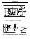
Isolate With Galvanic Impunity
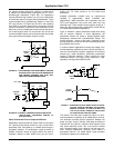
Do you require tried and true isolation? Then use
transformers; the IGT’s low gate requirements simplify the
design of independent, transformer-coupled gate-drive
supplies. The supplies can directly drive the gate and its
discharge resistor Figure 6, or they can simply replace the
level-shifting supplies of Figure 2. It’s good practice to use
pulse transformers in drive circuitry, both for IGT’s and
MOSFETs, because these components are economical,
rugged and highly reliable.
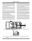
FIGURE 6A. PROVIDING HIGH ISOLATION AT LOW COST, PULSE
TRANSFORMERS ARE IDEAL FOR DRIVING THE
IGT. AT SUFFICIENTLY HIGH FREQUENCIES, C
1
CAN BE THE IGT’S GATE-EMITTER CAPACITANCE
ALONE.
FIGURE 6B. A HIGH-FREQUENCY OSCILLATOR IN THE TRANS-
FORMER’S PRIMARY YIELDS UNLIMITED ON-
TIME CAPABILITY.
In the pulse-on, pulse-off method Figure 6A, C
1
stores a
positive pulse, holding the IGT on. At moderate frequencies
(several hundred Hertz and above), the gate-emitter
capacitance alone can store enough energy to keep the IGT
on; lower frequencies require an additional external capacitor.
Use of the common-base n-p-n bipolar transistor to discharge
the capacitance minimizes circuit loading on the capacitor.
This action extends continuous on-time capability without
capacitor refreshing; it also controls the gate-discharge time
via the 1kΩ emitter resistor.
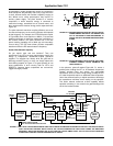
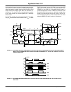
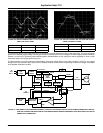
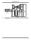
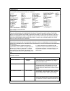
FIGURE 8. THIS 6-STEP 3-PHASE-MOTOR DRIVE USES THE IGT-DRIVE TECHNIQUES DESCRIBED IN THE TEXT. THE REGULATOR AD-
JUSTS THE OUTPUT DEVICES’ INPUT LEVELS; THE VOLTAGE-CONTROLLED OSCILLATOR VARIES THE SWITCHING
FREQUENCY AND ALSO PROVIDES THE CLOCK FOR THE 3-PHASE TIMING LOGIC. THE V/F RATIO STAYS CONSTANT
TO MAINTAIN CONSTANT TORQUE REGARDLESS OF SPEED.
ON
OFF
CONTROL
INPUT
1N914
1N914
2N5232
PULSE
TRANSFORMER
1k
C
1
IGT
+
-
IGT
+
-
ON OFF
1N914
CONTROL
INPUT
1N914 RC = 3µSEC
CR
CURRENT
SENSE
SIGNAL
ENABLE
LOWER
LEGS
SHUT DOWN
DRIVE
OSCILLATOR
VARIABLE
DC VOLTAGE
TIMING
AND DRIVE
VOLTAGE
ENABLE
ADJUST VOLTAGE
5V
24V
24V DC
220V AC
3φ 60Hz
THREE-PHASE
BRIDGE
RECTIFIER
LOW VOLTAGE
TRANSFORMER
RECTIFIER
FILTER
SWITCHING
REGULATOR
POWER SUPPLY
FOR CONTROL
CIRCUITS
VOLTAGE
CONTROLLED
OSCILATOR
MOTOR
CONTROL
LOGIC
OVERLOAD
PROTECTION
THREE-PHASE
IGT
INVERTER
TACHO-
METER
FEEDBACK
SIGNAL PATH ISOLATOR
EG: OPTOCOUPLIER PIEZO COUPLER
3φ
INDUCTION
MOTOR
III
I
I
Application Note 7511