


©2002 Fairchild Semiconductor Corporation Application Note 7511 Rev. A1
Use 6-Step Drive For Speed-Invariant Torque
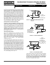
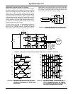
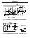
Figure 10A shows the inverter circuit configured for this
example. Diodes D
1
through D
6
carry the same peak current
as the IGTs; consequently, they’re rated to handle peak cur-
rents of at least 8.766A. However, they only conduct for a
short time (15
o
to 20
o
of 180
o
), so their average-current
requirement is relatively small.
External circuitry can control the IGT’s current fall time.
Resistor R controls t
F1
Figure 10B; there's no way to control
t
F2
, an inherent characteristic of the selected IGT. In this
example, a 4.7-kΩ gate-to-emitter resistor provides the
appropriate fall time. The choice of current-limiting inductor
L
1
is based on the IGT’s overload-current rating and the
action time (the sum of the sensor’s sensing and response
time and the IGT’s turn-off time) in fault conditions.
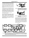
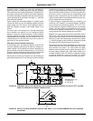
You could use a set of flip flops and a multivibrator to gener-
ate the necessary drive pulses and the corresponding 120
o
×
delay between the three phases in Figure 10’s circuit. A volt-
age-controlled oscillator serves to change the inverter’s out-
put frequency. In this circuit, IGTs Q
1
, Q
3
and Q
5
require
isolated gate drive; the drive for Q
2
, Q
4
and Q
6
can be
referred to common. If you use optocouplers for isolation,
you’ll need three isolated or bootstrap power supplies (in
addition to the 5V and 24V power supplies) to drive the IGTs.
Another alternative is to use transformer coupling.
165
o
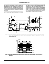
Conduction Prevents Shoot-Through
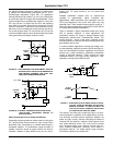
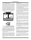
Consider, however, using Figure 11A’s novel, low-cost cir-
cuit. It uses a piezo coupler to drive the isolated IGT. As
noted, the coupler needs a high-frequency square wave to
induce mechanical oscillations in its primary side. The 555
oscillator provides the necessary 108-kHz waveform; its out-
put is gated according to the required timing logic and then
applied to the piezo coupler’s primary. The coupler’s rectified
output drives the IGT’s gate; the 4.7kW gate-to-emitter resis-
tor provides a discharge path for C
GE
during the IGT’s turn-
off. The circuit’s logic-timing diagram is shown in Figure 11B.
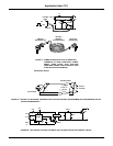
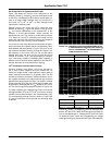
The piezo coupler’s slow response time Figure 12A contrib-
utes approximately 2
o
to the 15
o
to 20
o
turn-on/turn-off delay
needed to avoid shoot-through in the complementary pairs.
The corresponding collector current is shown in Figure 12B.
C
1
and its associated circuitry provide the remaining delay
as follows:
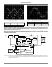
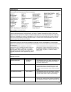
FIGURE 12A. THE PIEZO COUPLER’S SLOW RESPONSE IS NOT
A DISADVANTAGE IN THIS ARTICLE’S CIRCUIT. IN
FACT, IT CONTRIBUTES 2
o
TO THE REQUIRED 15
o
TURN-ON/TURN-OFF DELAY.
FIGURE 12B. THE DRIVEN IGT'S COLLECTOR CURRENT IS
SHOWN
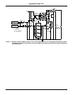
When Q
3
’s base swings negative, C
1
- at this time discharged -
turns on Q
5
. Once C
1
is charged, Q
5
turns off, allowing a drive
pulse to turn the IGT on. When Q
7
’s base goes to ground, Q
4
turns on and discharges C
1
, initiating the IGT’s turn-off. Figure
13 shows the motor current and corresponding line voltage
under light-load Figure 12A and full-load Figure 12B conditions.
TRACE VERTICAL HORIZONTAL
A 5V/DIV 200µSEC/DIV
B 5V/DIV 200µSEC/DIV
TRACE VERTICAL HORIZONTAL
A 3A/DIV 200µSEC/DIV
B 5V/DIV 200µSEC/DIV
Application Note 7511