


©2002 Fairchild Semiconductor Corporation Application Note 7511 Rev. A1
It’s impractical, however, to rate an inverter based on locked-
rotor current. You can avoid this necessity by adjusting the
switching regulator’s output voltage and by providing a fixed
output-current limit slightly higher than the maximum full-
load current. This way, the current requirements during start-
up will never exceed the current capability of an efficiently
sized inverter.
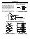
For example, consider a 2-hp, 3-phase induction motor spec-
ifying V
L
at 230V RMS and full-load current (I
LFL
) at 6.2A
RMS. For the peak current of 8.766A, you can select IGT
type D94FR4. This device has a reverse-breakdown SOA
(RBSOA) of 10A, 500V for a clamped inductive load at a
junction temperature of 150
o
C. A 400V IGT could also do the
job, but the 500V choice gives an additional derating safety
margin. You must set the current limit at 9A to limit the in-
rush current during start-up. Note that thanks to the IGT’s
adequate RBSOA, you don’t need turn-off snubbers.
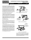
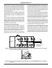
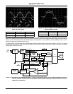
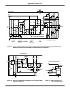
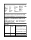
FIGURE 11A. PROVIDING PROPERLY TIMED DRIVE TO THE IGTS, THE CIRCUIT USES PIEZO COUPLING TO THE UPPER POWER
DEVICE. THE 3-TRANSISTOR DELAY CIRCUIT PROVIDES THE NEEDED 15
o
LAG TO THE LOWER IGT TO AVOID
CROSS CONDUCTION.
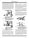
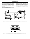
FIGURE 11B. THE TIMING DIAGRAM SHOWS THE 555’S 108-KHz DRIVE TO THE PIEZO DEVICE AND THE LATTER’S SLOW
RESPONSE.
1N914
NE555
4
7
8
3
21
56
2N3903
VCO &
TIMING
LOGIC
1000pF
2.7k
3.3k
1k
5V
0.001µF
5V
A4.7k
470
Q
7
B
1N914
4.7k
C
Q
8
2N3903
2N3903
Q
8
470
470
1N914
1N914
2N3903
1N914
D33030
D29E10
1N914
D94FR4
D94FR4
PIEZOCOUPLER
24V
24V
Q
3
Q
4
Q
5
Q
1
Q
2
4.7k
4.7k
10
10
22µF
C
1
DC BUS
φA
E
F
D
3
PZT61343
1k
470
2.5k
VOLTS
24V
F
24V
E
24V
D
C
B
A
TIME
TIME
TIME
TIME
TIME
5V
5V
5V
100kHz
Application Note 7511