


©2002 Fairchild Semiconductor Corporation Application Note 7511 Rev. A1
.
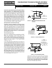
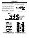
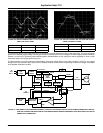
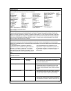
FIGURE 13A. MOTOR CURRENT AND VOLTAGE ARE SHOWN
HERE, FOR LIGHT LOADS
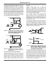
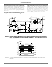
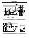
FIGURE 13B. MOTOR CURRENT AND VOLTAGE ARE SHOWN
HERE, FOR HEAVY LOADS.
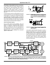
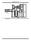
To complete the design of the 6-step motor drive, it’s necessary to consider protection circuitry for the output IGTs. The drive receives its
power from a switching supply already containing provisions for protection from line over-voltage and under-voltage and transient effects.
However, you still have to guard the power switches against unwanted effects on the output lines and the possibility of noise or other
extraneous signals causing gate-drive timing errors.
The best protection circuit must match the characteristics of the power switch and the circuit’s bias conditions. The IGT is very rugged
during turn-on and conduction, but it requires time to dissipate minority carriers when turning off high currents and voltages. An analysis
of the possible malfunction condition
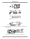
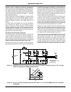
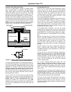
FIGURE 14. THE LOWEST COST SENSOR IMAGINABLE, A PIECE OF COPPER WIRE SERVES AS THE CURRENT MONITOR IN THIS SYS-
TEM. THE CHOPPED AND AMPLIFIED VOLTAGE DROP ACROSS THE WIRE TRIGGERS A GATE-DRIVE SHUT-OFF CIRCUIT
UNDER FAULT CONDITIONS.
TRACE VERTICAL HORIZONTAL
A 1A/DIV 1mSEC/DIV
B 50V/DIV 1mSEC/DIV
TRACE VERTICAL HORIZONTAL
A 3A/DIV 2mSEC/DIV
B 100V/DIV 2mSEC/DIV
AC
LINE
INPUT
HV
DISABLE
GATE DRIVE TURNOFF
HV
ADJUST
50 TO 320V DC
5V DC
UPPER 3
LOWER 3
dI/dt LIMIT
24V DC
CHOPPER
I LIMIT
10A
20A
ISOLATIONISOLATION
IGT
SWITCHES
MOTOR
CONTROL
AND
TIMING
ISOLATION
RECTIFIER
AND
FILTER
SWITCHING
POWER
SUPPLY
RECYCLE
TIME
COMPARATOR
AND LATCH
AC
AV = 100
ISOLATION
Application Note 7511