17
TURNING THE UPS OFF
To turn off the UPS:
While in Normal On-line mode, press the BYPASS button for one second. The UPS will go into
BYPASS MODE. Next, turn off the INPUT BREAKER. The unit will shut down immediately.
NOTE!
DURING SHUT DOWN, DO NOT PRESS ANY BUTTON SINCE UPS MIGHT BE RE-
ENERGIZED AND DELIVER POWER TO ITS OUTPUT UNEXPECTEDLY.
6.0 UPS SETUP CONFIGURATION
This section describes how to reconfigure the internal UPS setup options, by entering the
CONFIGURATION MODE. The setup parameters includes: UPS output voltage & enable or
disable GREEN MODE.
CAUTION
Never change the voltage settings when the UPS is ON and powering any connected loads.
NOTE!
Setting the UPS output voltage to 100 VAC will derate the UPS output VA and
WATTAGE ratings. Please refer to the SPECIFICATIONS located at the end of
this manual for information on your specific UPS model.
How To Place The UPS Into Setup/CONFIGURATION Mode
To put the UPS into configuration mode, press the “FUNTION/TEST” and “SET/ALARM
SILENCE” buttons at same time and hold them for one second. The unit will emit one audible
beep and then enter CONFIGURATION MODE.
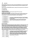
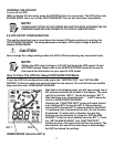
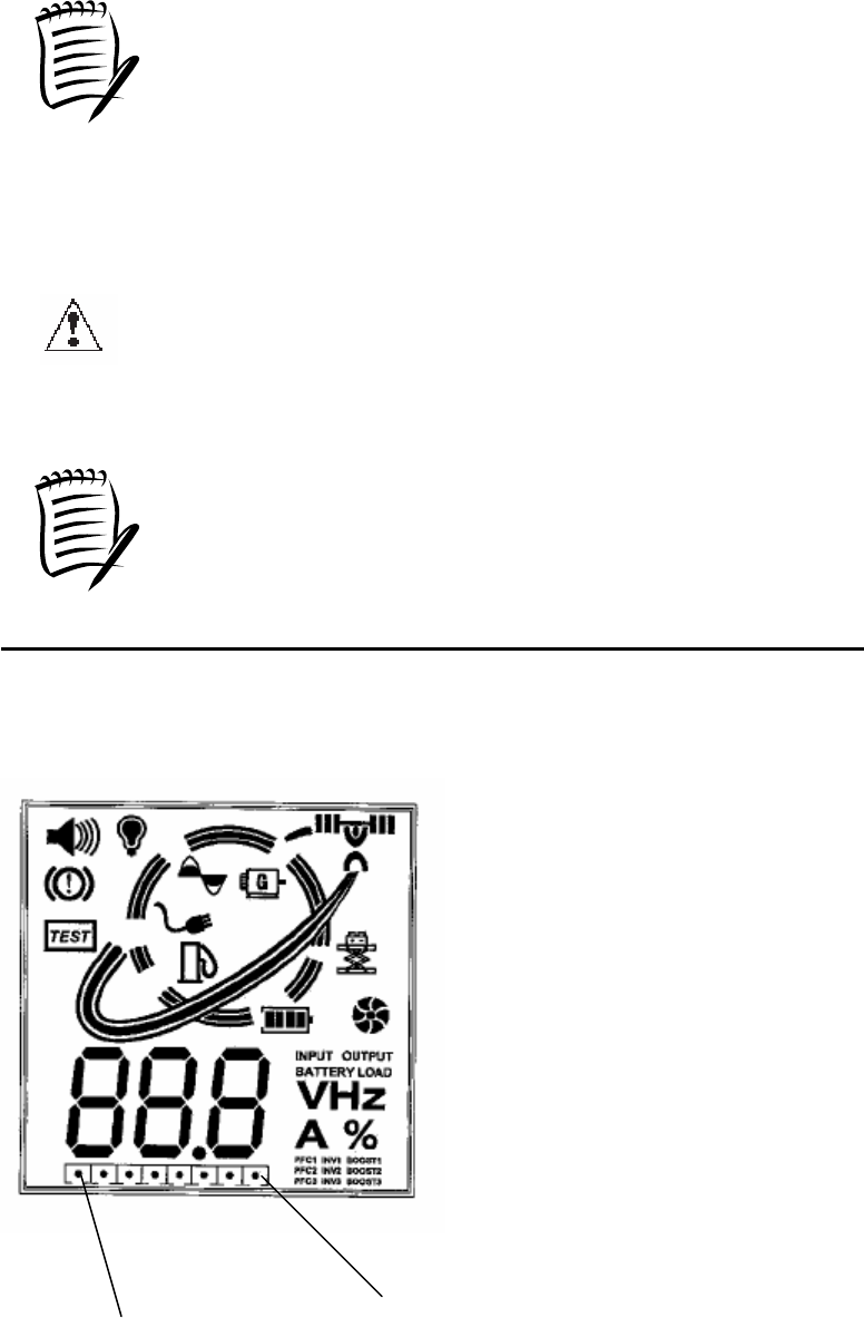
Note that on the display panel, you will see a single row, 8
BIT column located at the bottom of the display. The most
right bit is function “BIT 0”, the far left is status “BIT 7”.
Note that there is an illuminated dot “.” in BIT 0 when the
unit is in CONFIGURATION MODE.
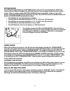
Pressing the “FUNCTION/TEST” button will move the dot
from function BIT 0 to function BIT 6. When selecting
function BIT 0 through BIT 6, observe whether status BIT
7 is selected (dot) or deselected (no dot,) for the function
bit selected. To select (dot) or deselect (no dot) the
function you are presently in, press the “SET/ALARM
SLIENCE” button to set or deselect function BIT 7. Press
the “SET/ALARM SLIENCE” and FUNCTION/TEST”
buttons at same time again and hold for one second. The
alarm buzzer will sound one short beep to acknowledge
the UPS has stored the settings.
GREEN MODE (Function BIT 3)
BIT 7
BIT 0
BIT 7


