


5
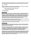
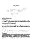
BLOCK DIAGRAM
2.0 CIRCUIT DESCRIPTIONS
INPUT FILTER
This internal UPS circuit provides surge protection, certified to meet IEC 61000-4-5 and IEC
801-5. It also filters both electro-magnetic interference (EMI) and radio frequency interference
(RFI). It minimizes surges or RFI interference present on the utility line.
CURRENT AND POWER FACTOR REGULATOR
In normal operation, this circuit converters utility AC power to regulated DC power for inverter
use. It ensures the input current maintains a sine waveform to minimize the amount of current
distortion that will be reflected to the utility. The XG Series UPS can tolerate a wide input
range and has an overload power factor regulator alarm to alert the user in the event the UPS
has an excessively heavy output load, while operation from a utility source with abnormally
low input voltage.
DC/DC CONVERTER
The DC/DC converter utilizes energy from battery and boosts up the DC bus voltage to a level
required by the inverter. This allows the inverter to operate continuously at optimum
efficiency and voltage. The converter has a patented circuit which reduces the amount of
ripple current and EMI interference to the battery.
DC/AC INVERTER
In normal on-line operation, the Inverter utilizes the regulated DC output to invert DC back into
clean, regulated sinewave AC power. When utility power fails, the inverter will receive its
energy from the battery through the DC/DC converter. In both modes of operation, the UPS
inverter is on-line and continuously generating clean, regulated AC output power to the load.
The XG Series has a pure sinewave output, which is produced with a Pulse Width Modulation
(PWM) Inverter. As a result, the UPS output is very stable, even with nonlinear loads.