


FS-8700-47 DNP 3.0 Driver Manual Page 38 of 51
FieldServer Technologies 1991 Tarob Court Milpitas, California 95035 USA Web: www.fieldserver.com
Tel: (408) 262 2299 Fax: (408) 262 2269 Toll Free: (888) 509 1970 email: support@fieldserver.com
Appendix A.13. DnpSubType
DNP objects often contain more than one element of information, e.g. Object 30, variation 1 is a 32-
bit analog input. When the DNP device is polled for data for this object the device returns a data
structure which contains a 32 bit value for the input and an 8 bit status byte indicating the input’s
quality. Alternatively the FieldServer defaults to the value subtype.
By using the value or flags in the field for dnpSubType you could have the FieldServer extract the
value or the status byte and place them in the data array associated with the Map Descriptor. In this
example it would have made no sense to try and extract a time as there is no time field associated
with object 30, variation 1.
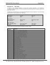
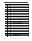
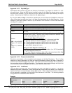
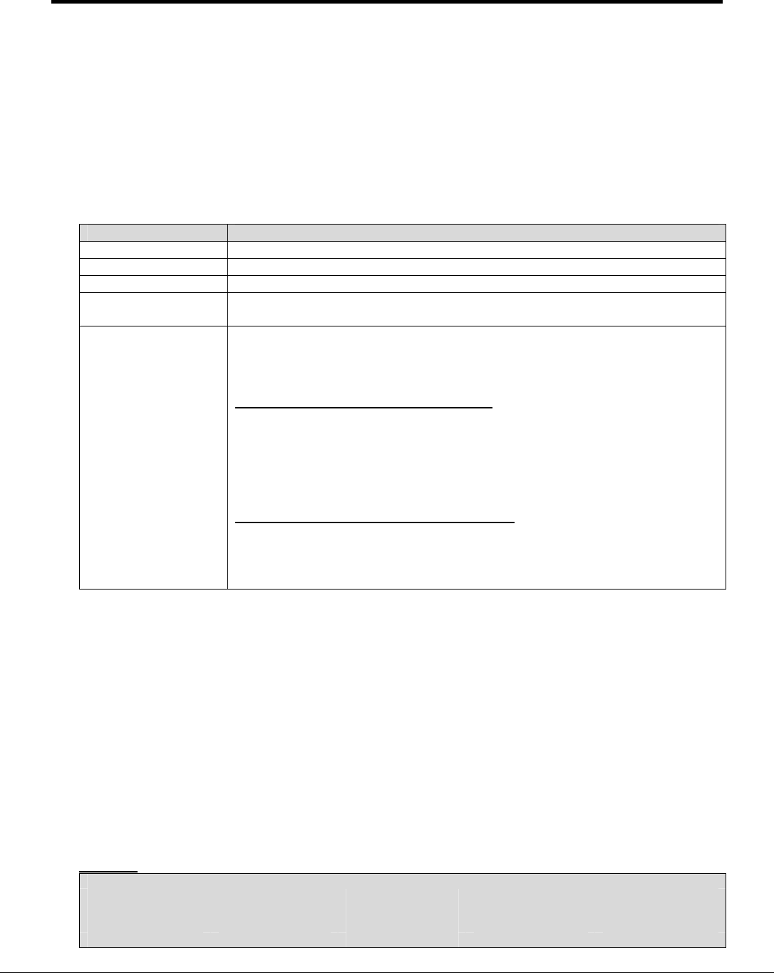
Permitted Values Description
Value The driver extracts the value of the object being read.
Flags The driver extracts the quality/status byte of the object.
Time1 The driver extracts the time field from the object.
Time2
The driver extracts a second time field from the object if the object has more
than one.
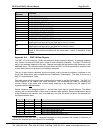
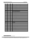
Combo
(NB - only valid with
Object 12, Variation
1;
Object 41, Variation
1 & 2)
Used with a write Map Descriptor with the dnpFunction set to 5 (Direct
Operation with no Ack). The driver uses multiple consecutive elements from
the data array to build the write command.
When used with Object 12 Variation 1.
The 1
st
array element is used as a byte to fill in the control code field.
The 2
nd
array element is used as a byte to fill in the count field.
The 3
rd
array element is used as a UINT32 to fill in the on time field.
The 4
th
array element is used as a UINT32 to fill in the off time field.
The status field is always set to zero.
When used with Object 41 Variation 1 & 2
The 1
st
array element is used as a INT32 (variation 1) or INT16 (variation2)
to fill in the requested value field.
The 2
nd
Array Element is used as a byte to fill in the control status field. (See
the definition of object 12 for a description of this field.)
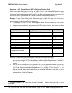
Appendix A.14. Communication Stats
The driver counts bytes on the connection and messages on the Map Descriptors. Thus if a Map
Descriptor is used to generate a poll then the transmit messages increment and when a response is
received, its received messages will increase. The byte count of these messages will be counted on
the connection and not on the Map Descriptor. The connection also counts messages and bytes that
form connection related messages such as link resets, confirms, acks, naks….
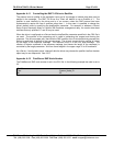
Appendix A.15. Link Reset
The Link Reset message forms part of the Data Link layer of the DNP 3.0 protocol. It is used to
establish and check a connection. When configured as a Client, the driver sends a Link Reset and
waits for the Server to respond before starting data transfer. When configured as a Server, the driver
will not respond to messages until the remote Client has sent a Link Reset. The following example
configuration will override this default behavior.
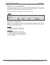
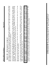
Example
// Server Side Connections
Connections
Port ,Baud ,Parity ,Protocol ,Application
P8 ,9600 ,None ,DNP ,NoLink