


FS-RA-CLX_SlotServer_Instruction_Manual_(T17011) Page 23 of 34
FieldServer Technologies 1991 Tarob Court Milpitas, California 95035 USA Web:www.fieldServer.com
Tel: (408) 262-2299 Fax: (408) 262-2296 Toll_Free: 888-509-1970 email: support@fieldServer.com
Appendix A. Advanced Topics
Appendix A.1. Description of Data Transfer Process
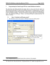
The data connection from the SlotServer to the Logix CPU consists of 496 bytes of input
and 496 bytes of output data. Of the 2 Map Descriptors specified, the one with the WRBC
function writes data to the Logix CPU filling its input data, and the one with the RDBC
function accepts the Logix CPU’s output data.
The Map Descriptor’s IO_Data_Type field organizes the 496 bytes into either Bytes (SINT),
Words (INT) or Double Words (DINT or REAL) reducing the number of elements that can be
transferred. Of the resulting number of elements, the first 4 are reserved for the IO image
header (Refer to Appendix A.2).
The SlotServer acts as a multiplexer when it sends data to the Logix-CPU and as a
demultiplexer when it receives data from the Logix-CPU.
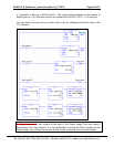
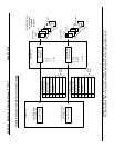
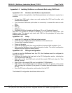
The diagram on the next page describes the SlotServer operation methodology:
For input data, the input data from the external device is placed into the 25 Data Arrays
numbered In_1 to In_25. The SlotServer sends the data from these Data Arrays over the IO
image connection one at a time by placing the block number at offset 2 of the image header
and the data from offset 4. The reverse happens at the Logix-CPU where a demultiplexer is
implemented in Ladder to route the data to each of the 25 CPU Tags.
For output data, the Logix-CPU has to place the data and block number into the Output
Image Tag and send it to the SlotServer. The SlotServer then demultiplexes the data by
placing it into the appropriate Out_x Data Array depending on the block number specified in
the IO image header.