


FS-RA-CLX_SlotServer_Instruction_Manual_(T17011) Page 27 of 34
FieldServer Technologies 1991 Tarob Court Milpitas, California 95035 USA Web:www.fieldServer.com
Tel: (408) 262-2299 Fax: (408) 262-2296 Toll_Free: 888-509-1970 email: support@fieldServer.com
Appendix A.5. Installing SlotServer on a Remote Rack using CNB Cards
Appendix A.5.1. Hardware and Software requirements
In order to perform this application, the following hardware and software is required as a
minimum:
• At least two 1756 racks, where one rack contains the CPU and the other rack
contains the SlotServer
• Two Controlnet CNB cards (with cable for connection) to connect the racks to each
other
• RSlinx
• RSLogix
• RSNetworx
• SlotServer EDS file (Available on SlotServer CD, or call Technical Support)
Note that it is possible to connect to SlotServer on a remote rack using other 1756
bridging cards. This chapter only deals with CNB, but the principles for using other
bridging cards are similar.
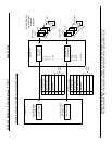
Appendix A.5.2. Setup
• Install the CPU and the first CNB card in the local rack.
• Install the second CNB card and the SlotServer in the remote rack.
• Connect the ControlNet Network
• Power up the racks
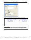
• Install the SlotServer EDS File using the RSLinx Hardware EDS Installation Tool.
• Make sure the SlotServer has a valid configuration loaded. The default configuration
shipped with the SlotServer should suffice.
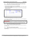
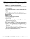
Appendix A.5.3. RSLogix configuration
In order to see the SlotServer from the CPU, the Hardware must be configured in
RSLogix as follows:
• Configure the cards in the local rack in the I/O Configuration section, including the
CPU and the local CNB card.
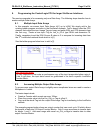
• Right click on the local CNB card and add the remote CNB card using the “New
Module” function.
• Right Click on the remote CNB card, and add the 1756 Backplane
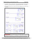
• Right Click on the 1756 Backplane and add the cards that are present in the remote
rack, including the SlotServer (As a generic I/O module-see earlier section on how to
do this)
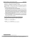
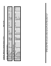
• Save the RSLogix configuration, and download it to the PLC.
The finished I/O configuration should look similar to this: