


Victoreen 875
Operators Manual
2-2
Under potential L.O.C.A. conditions of pressure and
temperature, the cable may expand as much as 11
inches per 100 feet.
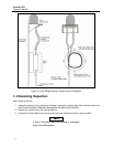
The distance from the pull box to the detector will be determined by the amount of flex hose used to seal
the detector cables. Additional information is found in the paragraph below Cable Sealing and in CABLE-
877 and 878-12-3 procedures in Appendix B.
Once the cables have been pulled and tested, the pull box cover must be bolted shut. To bolt the pull box
shut, follow the steps outlined in procedure 878-12-3 in Appendix B. Pull box material type and grade is
304 stainless steel.
Cable Sealing
In-containment cable is 878-1-9. This is special cable designed to withstand the potential high radiation
that may exist following a L.O.C.A. or similar event. In order to withstand the high pressure and moisture
generated during such an event, the entire cable length must be sealed so that moisture will not come in
contact with the cable. Cable specifications are listed below.
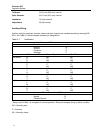
Specifications for Cable 878-1-9
Conductor #24 AWG, 19/36 Tinned Copper
Insulation Tefzel (BIWF)
Shield #36 AWG, Tinned copper brand, 90% Coverage
Jacket Tefzel (BIWF)
Outside Diameter 0.250 to 0.295 in
(6.35 to 7.49 mm)
Impedance 75 ohms nominal
Capacitance 22 pf/ft nominal
Dielectric Strength 7000 V minimum
Operating Voltage 2300 V maximum
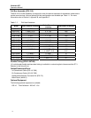
The following guidelines are based on the sealing method used during the qualification test. Stainless
steel Flex Hose 878-12-30, ¾ inch diameter x 18.5 inches long (with welded Swagelok connectors)
should be installed between the detector and pull box. Stainless steel tubing (¾ inch diameter) should be
installed from the pull box to the penetration for each cable. If a common stainless steel tubing run is
used, a one (1) inch diameter tube is recommended.
Seismic support and the sealing technique at
penetration vary with plant requirements.
Techniques and materials used are the customer's
responsibility.
Attach the stainless steel tubing to the pull box with compression fittings (¾ inch) and, after finger
tightening, tighten at least 1-¼ turns. The flex hose connection at the pull box is installed in the same
manner. The detector end of the flex hose is swaged to the cable connector backshell. This should not be
NOTE
NOTE