


Maintenance, Calibration, and Troubleshooting
Muting Stages of the Alarm Circuits
5
5-7
Conversely, during the ECS Test muting is definitely wanted, and the +12 V on pin 9 can easily overcome
the +2 V on pin 10.
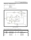
5.10 ESC Board (P/N 876A-1-92, Schematic 876A-1-3D)
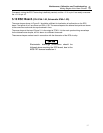
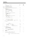
The wave-shapes shown in Figure 5-1 should be sufficient for localization of malfunction on the ECS
board. Test points A to S are shown on 876A-1-3D. The wave-shapes at the lettered test points are drawn
to the same time scale and also synchronized in time.
The wave-shape at the top of Figure 5-1 is the output at TP201. It is the main synchronizing waveshape
for the lettered wave-shapes, but it is drawn to a different time scale.
These wave-shapes are best used in connection with the discussion of the ECS circuitry.
Electrostatic discharge precautions should be
followed when servicing the ECS board, due to the
MOS FET devices located on it.
CAUTION