


Function Description
Functional Description
4
4-1
Section 4
Function Description
4.1 Functional Description
High-Range Containment Monitor Detector 877-1
The high-range containment monitor detector is an ion chamber detector that has the appearance of a
six-inch diameter domed cylinder about seven inches long, mounted on an L shaped bracket. Inside the
cylinder are two flange-mounted electrodes consisting of 31 flat, disk-shaped plates, each about four
inches in diameter, stacked, and mounted on disk rods. The 31 disks form two groups, interleaved with
each other, 16 collection disks and 15 signal disks. Because of the interleaving, they appear as only one
stack, but the collection disks are mounted on three collection disk-posts and the signal disks on three
signal disk-posts. Spacers on the posts keep the disks separated so they do not come in contact, and
clearance holes in the disks allow posts of the opposite polarity to pass through without contact. The
assembly has the appearance of a large air capacitor. The mounting posts are attached to the mounting
flange through insulating spacers, so the flange and housing will be neutral with respect to the charges
applied to the electrodes. The collecting diskposts are elongated beyond the last collecting disk to support
a cup-shaped liner having the same potential as the collecting disks, thus becoming part of the collector.
The whole assembly is covered by the six-inch diameter housing which contacts only the neutral
mounting flange. The mounting flange is pierced by three holes. One hole supports the exhaust tube used
for exhausting and back filling the chamber. The other two support two 2-pin connectors, one for each
electrode. One pin in each pair is connected to the neutral mounting flange. When the coaxial signal
cable is connected to this connector, the cable shield is connected to the neutral pin.
The entire chamber is filled with a mixture of helium (2%) and nitrogen at atmospheric pressure and
sealed.
The seal on this chamber must not be broken. To
do so would alter the calibration and specified
energy response of the system.
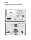
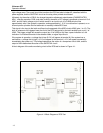
4.2 Readout Module 876A-1
Drawings 876A-1-3H and 876-1-3A serve as
interconnecting diagrams for tracing signals
between printed circuit boards. In addition, drawing
876-1-3A contains the main power supply
CAUTION
NOTE