


Victoreen 875
Operators Manual
1-4
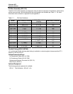
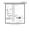
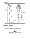
Pull Box Assembly (878-12-5)
The 878-12-5 Pull Box Assembly is designed to allow for thermal expansion of the detector cables and to
provide a service loop. Various optional pull-box configurations are available per Table 1-1. For more
information refer to Section 2, Appendix B, and Appendix C.
Table 1-1. Pull-box Variations
Model Inlet, Size and Location
Outlet, Size and
Location
Inlet/Outlet Orientation
878-12 1" 270° 2, ¾", 90° 180°
878-12-M 1 1" MNPT 270° 2, ¾", 90° 180°
878-12-M2 1" MNPT 270° 2, 1", 90° 180°
878-12-M3 1" 270° 1, 1", 90° 180°
878-12-M4 1" 270° 1, 1", 90° 90°
878-12-M5 ¾" 270° 2, ¾", 90 180°
878-12-M6 2, ¾" 0°/360° 2, ¾", 90 90°
878-12-M7 1" MNPT 270° 2, ¾", 90 90°
878-12-M8 2, ¾", 0° 1,1", MNPT, 90° 90°
878-12-M9 1,1" MNPT 90° 1, ¾" MNPT, 120° 150°
1, ½" MNPT, 210° 210°
878-12-M10 1,1" MNPT 2, ¾ 90° 0°
878-12-M11 2, ¾", 90° 1,1" MNPT 90° 0°
878-12-M12 2, ¾", 270° 1" MNPT, 0° 90°
Flexible Tubing (878-12-30TAB)
1.0 inch diameter flexible stainless steel tubing is available in various lengths to interconnect the 877-1
Detector to the first pull-box.
Cables/Connectors/Panel
In-Containment Cable: (878-1-9-TAB)
Ex-Containment Cable: (50-103-TAB)
Replacement Detector Connector Kit: (878-7-5)
Blank Panel: (844-8-5)
Optional Equipment
The following optional equipment is available:
878-10 Field Calibrator - 250 mCi
137
Cs