Victoreen 875
Operators Manual
5-12
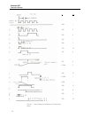
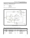
8 L Connected to 4 12 L
10 H
Since U202, (8, 9, 10) is
NOR
11 H Because 12 and 13 are L
12 H
Result: Output switches
from Low to High
This is the original condition. No
change takes place.
Notes:
1) Enable pulse assumed present, so 1 and 5 are L.
2) Initial condition assumes 12 and 10 L.
The truth table shows that no change in the output can occur without the presence of the enable pulse,
even though the monitoring signal indicates a fail condition. This is necessary because the ramp voltage
starts from zero during the ECS Test.
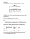
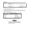
Table 5-2. Signal In Fail State (High Signal Input)
Pin 1 Voltage State Comments
10, U208 and 6, U202 H Fail state
9, U208 and 2, U202 L After inversion
1,5, U202 H No enable input
4, 8, U202 L Because of NOR action
3, 13, U202 L Because of NOR action
10, 12, U202 L Because of NOR action
Thus the circuit does not react to a fail signal input unless pins 1 and 5 are low.
If a problem cannot be resolved by applying the
troubleshooting and maintenance procedures
provided here, please contact Fluke Biomedical at
440.248.9300 for assistance.
NOTE


