


Maintenance, Calibration, and Troubleshooting
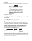
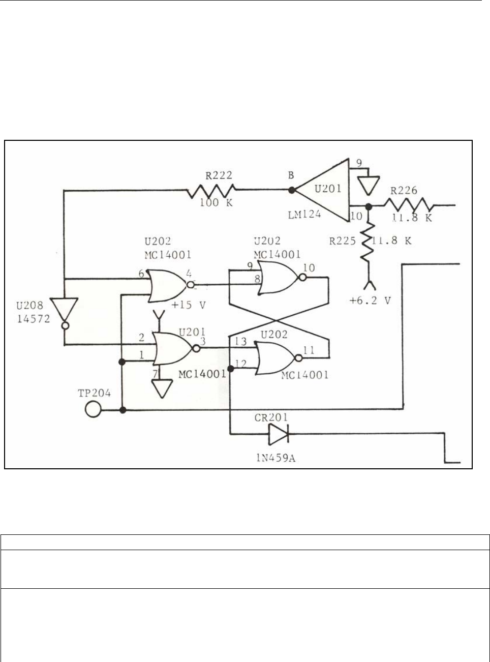
Operation of Latch Circuit
5
5-11
U202, pins 1, 5, L (Enable pulse active; i.e. low)
From these conditions, the following must hold true.
Pin Comment
4 Depends on 6
3 Depends on 2
Further analysis is contained in the truth table (Table 5-2).
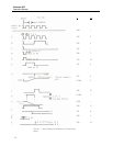
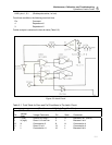
Figure 5-2. Latch Circuit
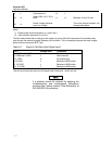
Table 5-1. Truth Table for Pass and Fail Conditions in The Latch Circuit
(Circuit assumed initially in Pass Condition)
Fail Condition Pass Condition
Pin
Voltage
State
Voltage Comments Pin State Comments
4 L (low) Since 6 is H (high) 4 H Because 6 is L (also 5)
3 H (high) Since 1 & 2 are Low 3 L Because 2 is H
13 H Connected to 3 8 H Connected to 4
11 L Since 13 is H 13 L Connected to 3
9 L Connected to 11 10 L Because 8 is H