FortiController-5103B mounting components Hardware installation
FortiController-5103B Session-Aware Load Balancer Guide
16 10-500-161552-20140822
http://docs.fortinet.com/
3 Hold the sides of the transceiver and slide it into the cage socket until it clicks into
place.
FortiController-5103B mounting components
To install a FortiController-5103B board you slide the board into a hub/switch slot in the
front of an ATCA chassis (usually slot 1 or 2) and then use the mounting components to
lock the board into place in the slot. When locked into place and positioned correctly the
board front panel is flush with the chassis front panel. The board is also connected to the
chassis backplane.
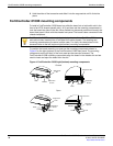
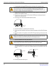
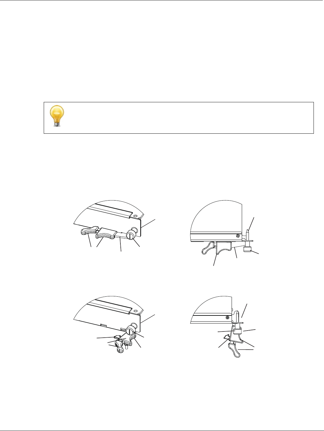
To position the board correctly you must use the mounting components shown in
Figure 4 for the right (bottom) of the FortiController-5103B front panel. The mounting
components on the left (top) of the front panel are the same but reversed. The
FortiController-5103B mounting components align the board in the chassis slot and are
used to insert and eject the board from the slot.
Figure 4: FortiController-5103B right (bottom) mounting components
FortiController-5103B boards are horizontal when inserted into a FortiGate-5060 chassis
and vertical when inserted into a FortiGate-5140-series chassis. The inserting and
removing procedures are the same in either case. For clarity the descriptions in this
document refer to the left (top) and right (bottom) mounting components.\
Closed
Open
Alignment
Pin
Retention
Screw
Lock
Handle
Alignment Pin
Retention
Screw
Lock
Handle
Handle
Hook
Alignment Pin
Retention
Screw
Lock
Hook
Alignment
Pin
Retention
Screw
Lock
Handle


