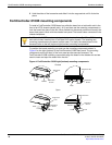
Front panel LEDs and connectors FortiController-5103B system
FortiController-5103B Session-Aware Load Balancer Guide
8 10-500-161552-20140822
http://docs.fortinet.com/
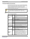
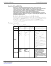
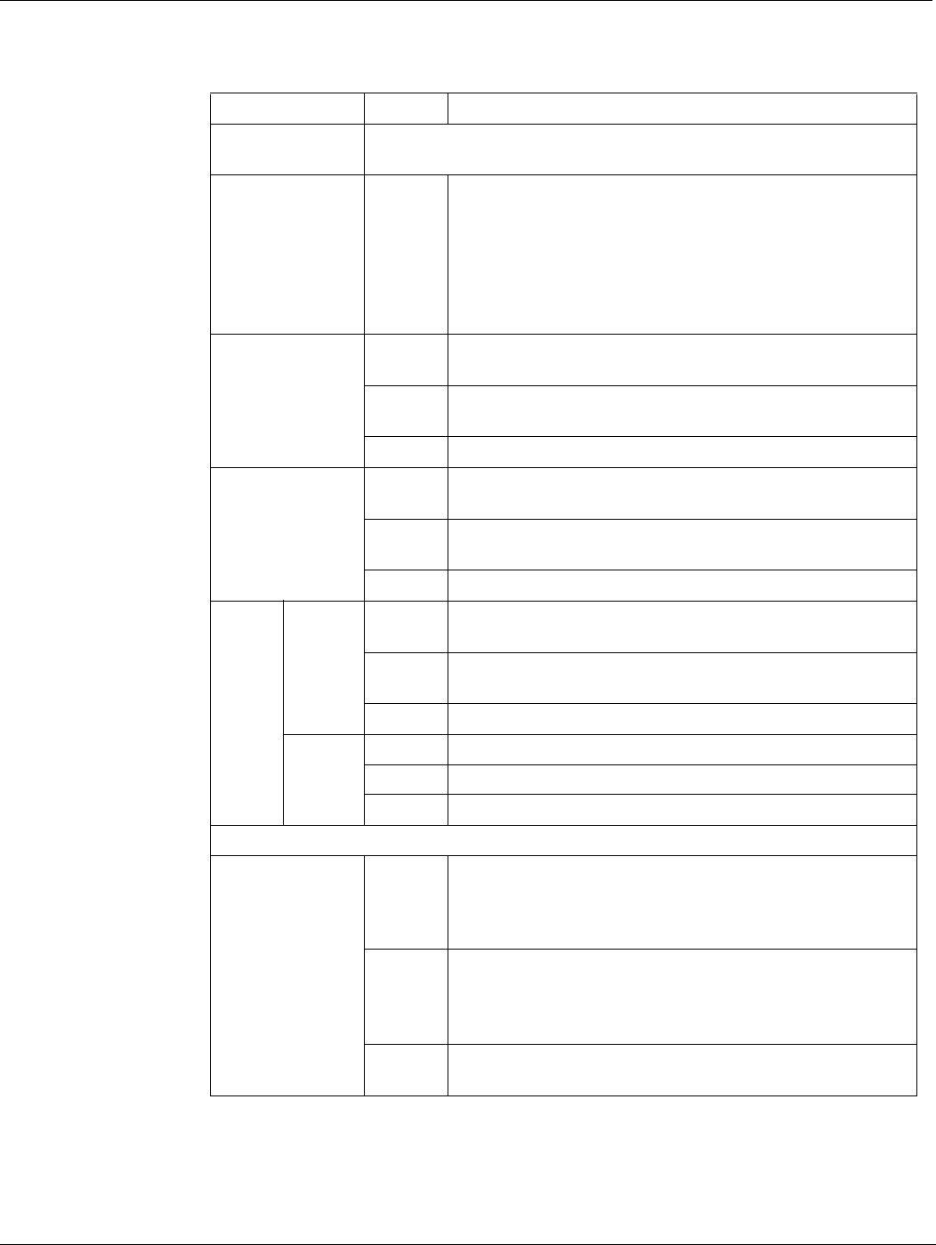
SH1
Not used in the default configuration. See “About the SH1 and SH2
LEDs” on page 9.
SH2
Green or
Flashing
Green
Network activity between the FortiController-5103B
board and one of the shelf managers across the chassis
backplane. If the FortiController-5103B board is installed
in chassis slot 1, this LED indicates a connection to shelf
manager 2. If the FortiController-5103B board is installed
in chassis slot 2, this LED indicates a connection to shelf
manager 1.
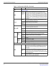
1 to 8
Green The correct cable is connected to the interface and the
connected equipment has power.
Flashing
Green
Network activity at the interface.
Off No link is established.
B1 and B2
Green The correct cable is connected to the interface and the
connected equipment has power.
Flashing
Green
Network activity at the interface.
Off No link is established.
MGMT
Link/Act
(Left
LED)
Solid
Green
Indicates this interface is connected with the correct
cable and the attached network device has power.
Blinking
Green
Indicates network traffic on this interface.
Off No Link
Speed
(Right
LED)
Green Connection at 1 Gbps.
Amber Connection at 100 Mbps.
Off Connection at 10 Mbps.
The unlabeled interface beside the MGMT interface is not used.
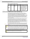
IPM
Blue The FortiController-5103B is ready to be hot-swapped
(removed from the chassis). If the IPM light is blue and no
other LEDs are lit the FortiController-5103B board has
lost power
Flashing
Blue
The FortiController-5103B is changing from hot swap to
running mode or from running mode to hot swap. This
happens when the FortiController-5103B board is starting
up or shutting down.
Off Normal operation. The FortiController-5103B board is in
contact with the chassis backplane.
Table 2: FortiController-5103B LEDs (Continued)
LED State Description


