


Foundry NetIron M2404C/M2404F Metro Access Switches
January 2007 © 2007 Foundry Networks, Inc. 6
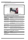
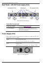
Component Description
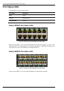
GigE Dual-Mode Ports
Two dual-mode1000baseX interface (SFP) or 10/100/1000BaseT
(RJ45) marked 25 and 26.
Enhanced GigE Ports
Two 1000baseX interface (SFP) marked 27 and 28. Please note
that the SFP transceivers are inserted into the slot, belly-down, as
shown in figure above.
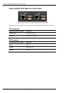
Console Management
Port
RJ45 socket for CLI configuration and management of the unit.
Ethernet Management
Port
RJ45 socket with 10/100 Mbps LAN speed auto sensing for out-
of-band Ethernet management and software update.
RST Button
Reset button. To avoid accidental activation, the button is recessed
behind the panel. Press with a pin or a similar narrow object.
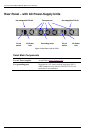
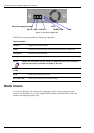
Unit LEDs
The following descibes the LEDs on the chassis.
Label Function Indication
ETH
Ethernet management interface
status.
• Off – Link down.
• Green – Link up.
• Blinking green – activity.
FLT
Platform HW fault.
• Off – Switch hardware OK.
• Red – CPU can't boot.
• Blinking red – Failure during BIST.
MNG
CPU controller is processing
management tasks.
• Off – No management activity.
• Green – Management activity.
STS
General platform status.
• Off – Platform processing boot loader.
• Green fast blink – Platform initializing
application.
• Green – Normal operation.
PSU #1
PSU #1 status.
• Green – PS #1 functioning.
• Red – Problem in PS #1 or no power
feed.
• Off – PS #1 removed.
PSU #2
PSU #2 status.
• Green – PS #2 functioning.
• Red – Problem in PS #2 or no power
feed.
• Off – PS #2 removed.