


Foundry NetIron M2404C/M2404F Metro Access Switches
January 2007 © 2007 Foundry Networks, Inc. 16
For each DC power block a set of a minimum 2x18AWG cables shall be used with suitable end
terminal legs matching the conductor’s gauge. Use a RED lead to for the positive conductor and
a BLACK lead for the negative conductor. It is recommended that only UL listed components
be used for the DC power connections.
CAUTION
For a DC system, use a grounding wire of at least 10 American Wire
Gauge (AWG). The 10 AWG wire should be attached to an agency-
approved crimp connector, crimped with the proper tool. The crimp
connector should allow for securement to both ground screws on the
enclosure.
CAUTION
For the DC input circuit to the system, make sure there is a Listed 10 amp
circuit, minimum -48Vdc, double pole, on the input to the terminal block.
The input wiring for connection to the product should be Listed copper
wire, 18 AWG, marked VW-1, and rated minimum 90 deg. C.
NOTE
There is no connection needed for GND. Only the ground wire is connected to
the Grounding Stud.
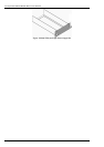
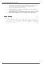
Grounding the Switch
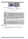
WARNING
Before connecting power to the switch, make sure that both grounding
posts in the rear panel are firmly connected to a reliable ground through a
#10 AWG grounding wire terminated by a UL-listed two-hole long-barrel
5/8 10 AWG compression lug with hole size and spacing as shown in Figure
15
below.
The Burndy YAZV10-2TC14 or an equivalent UL-listed two-hole
compression lug is recommended.
16 mm
(5/8”)
φ6.4 mm
(1/4”)
Figure 15: Compression Grounding Lug
To connect the switch to the ground, proceed as follows:
1.
Prepare a minimum #10 AWG grounding wire terminated by a crimped two-hole lug
with hole diameter and spacing as shown in Figure 15
. Use a suitable crimping tool to
fasten the lug securely to the wire. Adhere to your company’s policy as to the wire gauge
and the number of crimps on the lug.
10 AWG