


Debugger Components
Visualization Utilities
146
Microcontrollers Debugger Manual
Instruments
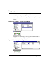
When you first add an instrument, it is in “move mode”. Place it at the desired location on
the workspace. All new instruments are set to their default attributes. To configure an
instrument, right-click on an instrument and choose Properties, or double click on it. All
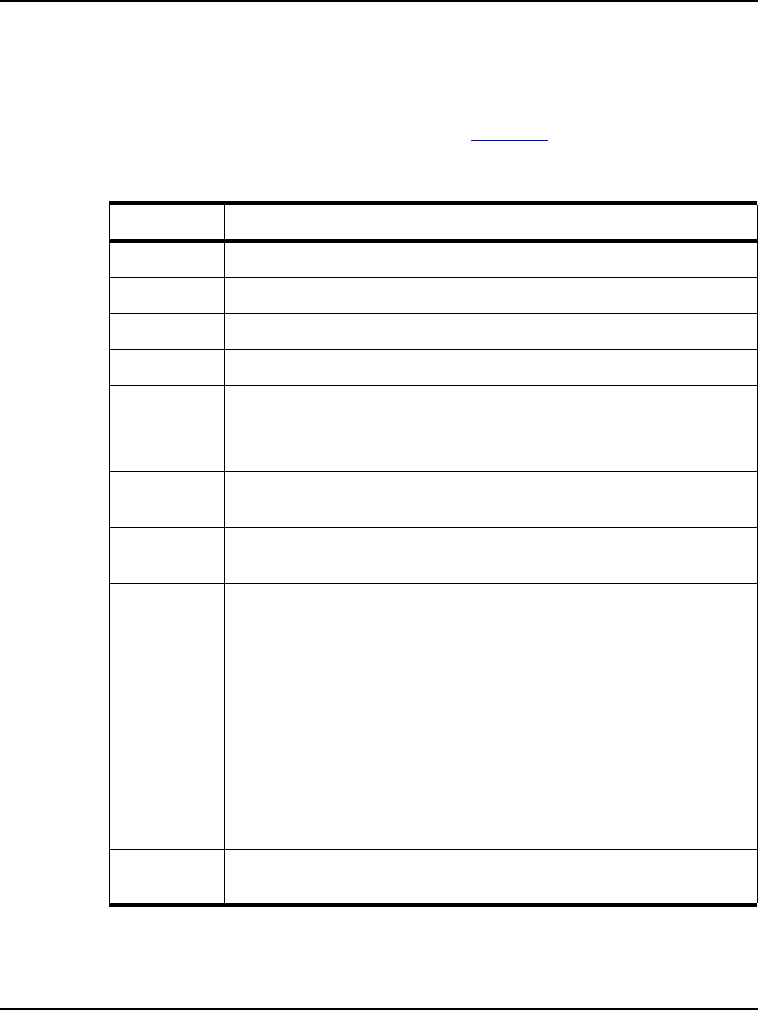
instruments have the common attributes shown in Table 3.46
.
:
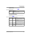
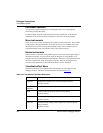
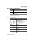
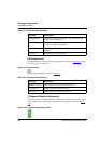
Table 3.46 Instruments Properties Attributes
Attribute Description
X-Position Specifies the X-coordinate of the upper left corner.
Y-Position Specifies the Y-coordinate of the upper left corner.
Height Specifies the instruments height.
Width Specifies the instruments width.
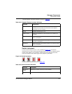
Bounding
Box
Specifies the look of the bounding box.
Available displays are: No Box, Flat (outline only), Raised, Sunken,
Etched, and Shadowed.
Background
color
Defines the color of the instrument’s background. The checkbox enables
to set a color or let the instrument be transparent.
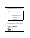
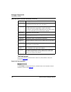
Kind of Port Specifies the kind of port to be used to get the value to display. The
location must be specified in the Port to Display field.
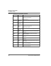
Port to
Display
Defines the location of the value be used for the instrument’s
visualization.
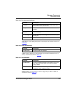
Here are some Examples:
Substitute:
TargetObject.#210
Subscribe:
TargetObject.#210
Subscribe:
PORTB.PORTB (check exact spelling using Inspector)
Variable:
counter
Register:
SP
Memory:
0x210
Size of Port If you use the Memory Port, you can also specify the width of memory to
display (up to 4 Bytes).