


HC08 Full Chip Simulation
Configuration Procedure
298
Microcontrollers Debugger Manual
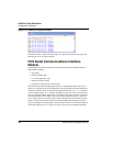
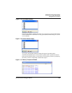
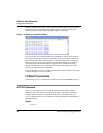
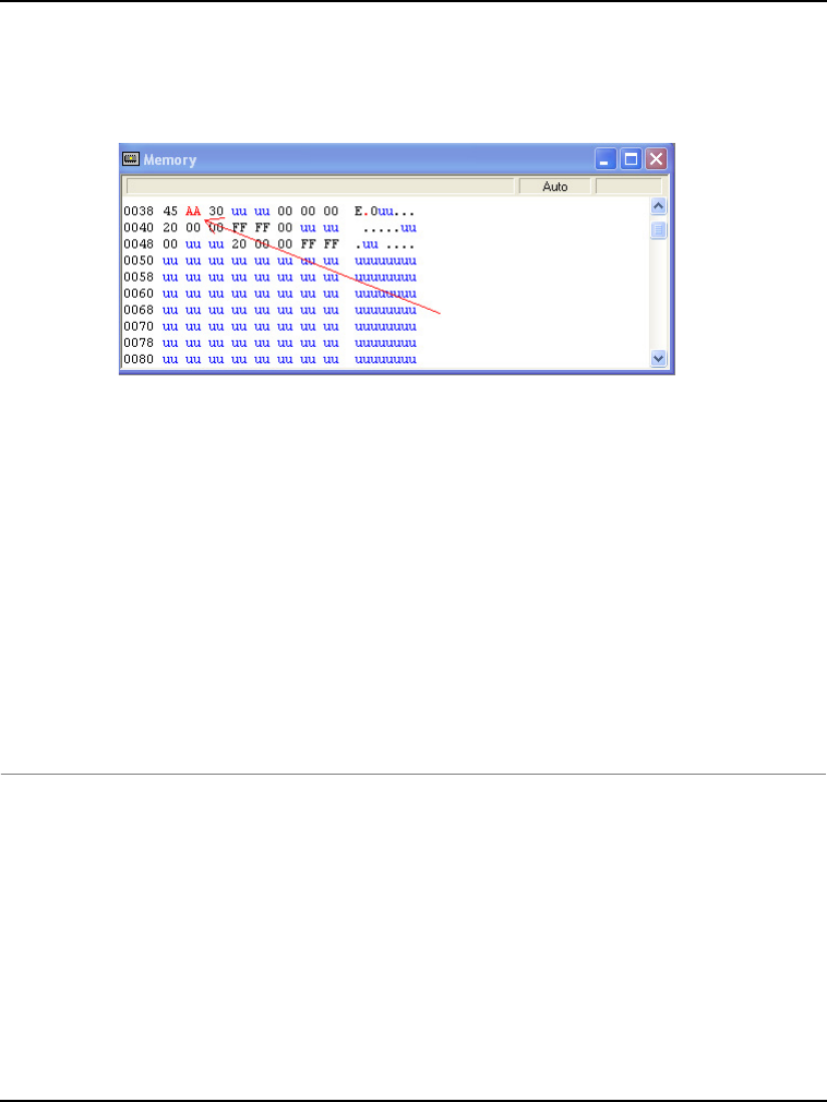
After the simulated SLIC input is received, the first queued-in packet is passed from the
data buffer into the corresponding SLIC module registers. It can be observed in the
Memory Window by displaying the appropriate register location there.
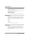
Figure 11.43 Memory Component Window
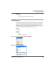
The user can also observe different SLIC flags in the Memory window. If the module is
run in Flag Polling mode, poll the flag corresponding to the expected SLIC event. If the
SLIC interrupts are enabled, the FCS jumps to an appropriate subroutine, as long as the
SLIC interrupt vectors are properly defined. Note that the SLIC State Vector Register
reflects the specific SLIC interrupt that was triggered. CPU overhead for servicing
different LIN interrupts can be significantly decreased by monitoring the state of this
register from within the interrupt subroutine.
For more information on how to configure SLIC module for desired operation, refer to the
Freescale manual for your microprocessor.
FCSSLIC Commands
The following FCSSLIC commands are available for use with the M68HC08 processor.
SLCCLR Command
The SLCLR command can be used to flush the input and output buffers for SLIC
simulation. This resets the buffers and clear out all packets. Notice that if the SLIC is
currently shifting a value, this command allows the SLIC to finish the transfer. See
SLCDI command and SLCDOUT command for accessing the input and output buffers of
the SLIC interface.
Syntax
>SLCCLR