


2
3. Names and Functions of Components 2-9
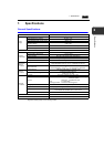
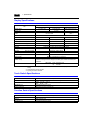
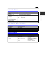
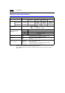
Specifications
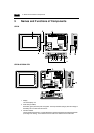
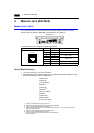
4. Option unit connector (CN1)
This is the connector where the option unit UG230A-DCL is mounted.
5. Battery holder
Contains a backup battery for SRAM and clock.
When the battery voltage drops, replace the battery with a new one (UG30P-BT).
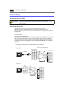
6. Modular jack connector (MJ1)
This is used for screen data transfer and connection with temperature controller, barcode reader,
UG00P-MR, etc.
7. Modular jack connectors (MJ2)
This is used for connection with the PLC.
With the option unit UG230A-DCL mounted, the modular jack allows you to connect a barcode
reader, serial printer, etc.
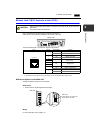
8. USB-B (slave port)
This is the connector for screen data transfer.
9. USB-A (master port)
This is the connector where a printer or a CF card reader/writer is connected.
10. Power supply terminal block
Supplies the power (24 VDC) to the UG230.
11. Mounting holes
Used for inserting fixtures when securing the POD to the mounting panel.
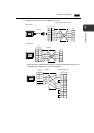
12. DIP switch
This is used for setting the terminating resistors of the MJ1/MJ2 RS-422/485 signal line.
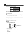
13. Slide switch
This is used for switching between the RS-232C and RS-422 ports for the MJ2.
14. Add-on memory connector (MEMORY) (optional)
With the option unit UG230A-DCL mounted, this is used for mounting an optional FLASH memory
cassette (UG230P-D4).
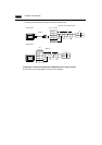
15. PLC communication connector (CN1) (optional)
With the option unit UG230A-DCL mounted, this is used for connecting the UG230 and a PLC or
an external control unit (computer, custom controller, etc.).
16. CF card connector (CF) (optional)
This is the connector where the CF card is inserted when the option unit UG230A-DCL is installed.
17. 10BASE-T connector (LAN) (optional)
With the option unit UG230A-DCL mounted, this is used for Ethernet connection.