


Features
A26361-D1419-Z120-1-7419 English - 7
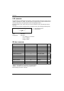
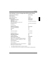
PCI bus resources
PCI slots
The following table shows an overview of the PCI slots:
PCI slot 64bit/32b
it
Frequency
in MHz
PCIX Description
1 64 bit 100/133 yes 64 bit PCI bus slot
2 64 bit 100 yes 64 bit PCI bus slot
3 64 bit 100 yes 64 bit PCI bus slot, prepared for
ZCR (= Zero Channel RAID)
4 64 bit 100 yes 64 bit PCI bus slot, prepared for
riser card E313
5 64 bit 33 no 64 bit PCI bus slot
PCI IRQ line x - Assignment of the PCI interrupts
PCI IRQ Line x defines which ISA interrupts are used for the separate PCI slots.
If you select Auto in the BIOS setup, the interrupts are assigned automatically and no further
settings are required.
Multifunctional PCI boards or boards with an integrated PCI-to-PCI bridge can use several PCI
interrupts (INTA#, INTB#, INTC#, INTD#). Monofunctional PCI boards (default) only use one PCI
interrupt (INTA#) per PCI slot.
The PCI interrupts INTA#, INTB#, INTC# and INTD# are available for each PCI slot, however only 2
are routed further for PCI slot 5, as A and C as well as B and D are interrelated.
The same interrupt can be assigned simultaneously to several PCI boards. You should avoid this
condition due to reduced performance.
If you use a setting other than Auto, the Plug&Play functionality of the system BIOS for the
corresponding PCI boards is deactivated.
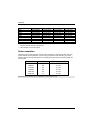
Auto The PCI interrupts are assigned automatically in accordance with the Plug&Play
guidelines.
Disabled No ISA interrupt is assigned to the PCI interrupt.
3, 4, 5, 6, 7, 9, 10, 11, 12, 14, 15
The selected ISA interrupt is assigned to the PCI interrupt. You may not select an
ISA interrupt that is used by a component on the mainboard (e.g. controller) or an
ISA board.