


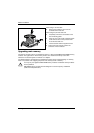
Add-on modules
A26361-D1419-Z120-1-7419 English - 17
Add-on modules
!
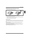
For all steps described in this chapter pull the power plug out of the mains outlet!
1
2
3
4
5
6
7
8
9
10
11
12
13
14
15
16
17
18
19
20
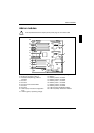
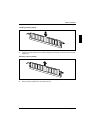
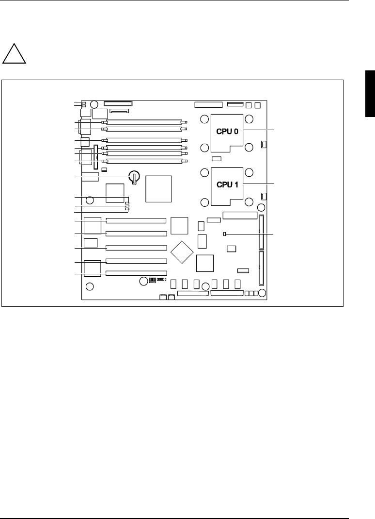
1 = Socket for processor 1 (CPU 0)
2 = Socket for processor 2 (CPU 1)
3 = Heartbeat-LED (blinking): "BMC is
activated"
4 = PCI slot 1
5 = PCI slot 2
6 = PCI slot 3: Zero Channel RAID
7 = PCI slot 4
8 = PCI slot 5
9 = LED L3 (red): "Processor configuration
error“
10 = LED L2 (green): "Operating voltage“
11 = LED L1 (yellow): "Auxiliary voltage“
12 = Battery
13 = Memory bank 0, module A
14 = Memory bank 0, module B
15 = Memory bank 1, module A
16 = Memory bank 1, module B
17 = Memory bank 2, module A
18 = Memory bank 2, module B
19 = LED L5 (blue): identification display
20 = LED L4 (amber): Global error indicator