


ETERNUS DX80 S2/DX90 S2 Disk storage system User’s Guide -Site Planning-
Copyright 2013 FUJITSU LIMITED P3AM-4822-12ENZ0
8
List of Figures
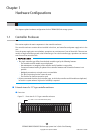
Figure 1.1 Front view of a 2.5" type controller enclosure.............................................................................................. 11
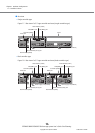
Figure 1.2 Rear view of a 2.5" type controller enclosure (single-controller type).......................................................... 12
Figure 1.3 Rear view of a 2.5" type controller enclosure (dual-controller type)............................................................ 12
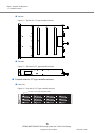
Figure 1.4 Top view of a 2.5" type controller enclosure ................................................................................................ 13
Figure 1.5 Side view of a 2.5" type controller enclosure ............................................................................................... 13
Figure 1.6 Front view of a 3.5" type controller enclosure.............................................................................................. 13
Figure 1.7 Rear view of a 3.5" type controller enclosure (single-controller type).......................................................... 14
Figure 1.8 Rear view of a 3.5" type controller enclosure (dual-controller type)............................................................ 14
Figure 1.9 Top view of a 3.5" type controller enclosure ................................................................................................ 15
Figure 1.10 Side view of a 3.5" type controller enclosure ............................................................................................... 15
Figure 1.11 Front view of a 2.5" type drive enclosure..................................................................................................... 18
Figure 1.12 Rear view of a drive enclosure (single-IOM type) ........................................................................................ 18
Figure 1.13 Rear view of a drive enclosure (dual-IOM type)........................................................................................... 19
Figure 1.14 Top view of a 2.5" type drive enclosure........................................................................................................ 19
Figure 1.15 Side view of a 2.5" type drive enclosure....................................................................................................... 19
Figure 1.16 Front view of a 3.5" type drive enclosure..................................................................................................... 20
Figure 1.17 Rear view of a drive enclosure (single-IOM type) ........................................................................................ 20
Figure 1.18 Rear view of a drive enclosure (dual-IOM type)........................................................................................... 20
Figure 1.19 Top view of a 3.5" type drive enclosure........................................................................................................ 21
Figure 1.20 Side view of a 3.5" type drive enclosure....................................................................................................... 21
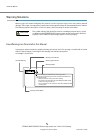
Figure 1.21 Enclosure connection path (dual-controller type) ....................................................................................... 22
Figure 1.22 Enclosure connection path (single-controller type)..................................................................................... 23
Figure 1.23 Power distribution unit (AC200-240V, 1U, Max 2 enclosures connection) ................................................... 24
Figure 1.24 Power distribution unit (AC200-240V, 2U, Max 6 enclosures connection) ................................................... 25
Figure 1.25 Power distribution unit (AC200-240V, 2U, Max 8 enclosures connection) ................................................... 26
Figure 2.1 2.5" type controller enclosure dimensions................................................................................................... 31
Figure 2.2 3.5" type controller enclosure dimensions................................................................................................... 32
Figure 2.3 2.5" type drive enclosure dimensions.......................................................................................................... 33
Figure 2.4 3.5" type drive enclosure dimensions.......................................................................................................... 34
Figure 2.5 Installation area and service area ............................................................................................................... 36
Figure 2.6 Power distribution unit (1U)........................................................................................................................ 40
Figure 2.7 Power distribution unit (2U)........................................................................................................................ 41
Figure 2.8 Breaking characteristics of distribution board circuit protectors .................................................................. 42
Figure 2.9 Example of a power supply connection using a power distribution unit (1U).............................................. 43
Figure 2.10 Example of a power supply connection using a power distribution unit (2U).............................................. 44
Figure 2.11 Example of a power supply connection without power distribution units.................................................... 45
Figure 3.1 Single path connection (direct connection)................................................................................................. 48
Figure 3.2 Single path connection (switch connection)................................................................................................ 49
Figure 3.3 Multipath connection (direct connection) ................................................................................................... 49
Figure 3.4 Multipath connection (switch connection).................................................................................................. 50
Figure 3.5 Connection that satisfies the system requirements (for availability)........................................................... 51
Figure 3.6 Connection that satisfies the system requirements (for enhanced performance)........................................ 51
Figure 3.7 Example of non-supported connection configuration (when multiple types of
remote interfaces are installed in the same ETERNUS DX Disk storage system) .......................................... 52
Figure 3.8 Example of supported connection configuration (when multiple types of
remote interfaces are installed in the same ETERNUS DX Disk storage system) .......................................... 52
Figure 3.9 FC connection for remote copy (redundant path)........................................................................................ 53
Figure 3.10 FC connection for remote copy (using lines)................................................................................................ 53