


STARTERKIT MB91360
Chapter 6 Evaluation Board Hardware
© Fujitsu Microelectronics Europe GmbH - 23 - UG-910006-13
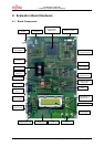
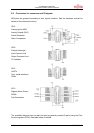
The evaluation board provides various IO-signals, which can be connected to external
devices. The controller resource functions are available on the connectors JP14, JP15, JP16
and JP20.
External peripheral devices can be connected via the address/data bus on JP24 and JP25.
For more information please refer to the following pin assignments and the schematics in the
appendix.
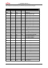
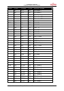
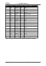
6.2 Overview of Jumpers
Jumper Description Standard Setting
Jumper Position
JP1 Main Vcc Net for MCU Closed (Vcc supplied) Closed
JP2 32kHz-Oscillator GND (X0A disabled) (2-3 closed) Right
JP3 4 MHz-Oscillator X0 (Active) (1-2 closed) Left
JP4 LPF for 32kHz-Oscillator Vcc (Enabled) (2-3 closed) Up
JP5 Clock Select Pin Vcc (4 MHz) (2-3 closed) Up
JP6 Hardware Standby Pin Vcc (Disabled) (2-3 closed) Up
JP7 Select Source MD0 Vcc (PAL) (2-3 closed) Up
JP8-10 Test Mode Enable Open (no test mode) Open
JP13 LED enable Closed (LEDs active) Closed
JP17-19 Analog Supply Voltage Closed (A/D active) Closed
JP22-23 Driver Supply Voltage Closed (Driver active) Closed
JP26 Serial Output 0 enable Closed (enabled) Closed
JP27 Serial Input 0 enable Closed (enable) Closed
JP28-29 CAN0 driver enable Closed (enable) Closed
JP30,31 USER-buttons enable Closed (enable) Closed
JP32 Ext. UART int. enable Open (disable) Open
JP33 DTR reset enable Open (disable) Open
JP34 Power-up mode GND (Monitor mode) (1-2 closed) Down
MD2 Mode-Pin 2 GND On (Upper Dip Pos)
MD1 Mode-Pin 1 GND On
MD0 Mode-Pin 0 GND On
BOOT Boot-Pin GND On
Table 1: Selection jumpers on MB91360 Starterkit