


STARTERKIT MB91360
Chapter 7 Appendix
© Fujitsu Microelectronics Europe GmbH - 31 - UG-910006-13
7.2 Tool options for own projects
Valid load module files for MB91360 devices can only be achieved if the language tool
configuration is appropriate. If you use the provided samples or templates, you do not have
to worry about these settings.
The most convenient way to create own projects is to copy the provided Template-Project
from the sample-directory and use it as “blank sheet”. However, if you intend to create
projects “from scratch” without the template, the following settings are important.
Target MCU (“Project – Setup” menu) : make sure “MB91FV360” or “MB91F362” is selected
as the target MCU device.
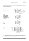
Linker Settings (“Project – Setup tool options – Linker – Disposition”) : MB91360 devices
use a fixed memory map for code stored in Flash-ROM or data assigned to the internal
RAM. In addition, certain Flash-sectors have special meanings, such as the boot-sector
(application always starts from 0F4000) or the kernel of the debugger stored from 0F0000.
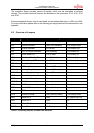
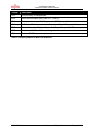
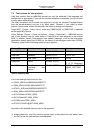
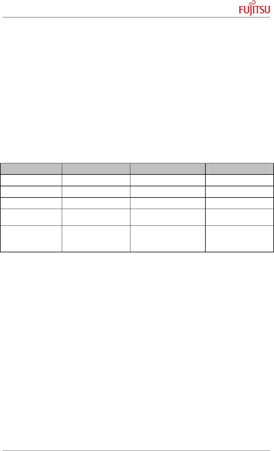
Therefore, make sure the following memory map is applied:
Memory Type Used for Area Sections
Data RAM Stack 3D000..3DFFF STACK
Data RAM Variables 3E000..3FFFF DATA, INIT
Flash ROM User Code 080000..0EFFFF CODE
FlashROM Kernel 0F0000..0F3FFF
1.1.1.1.1 Reserved !
FlashROM Boot-Sector,
constants and
vectors
0F4000..0FFFFF START, CONST,
@INIT, VECTORS
Table 4: Memory Map
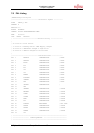
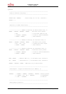
Your linker settings should look like this:
-ro CODE_AREA=0x00080000/0x000EFFFF
-ro ROM_AREA=0x000F4000/0x000FFFFF
-ra STACK_AREA=0x0003D000/0x0003DFFF
-ra RAM_AREA=0x0003E000/0x0003FFFF
-sc STACK/Stack=STACK_AREA
-sc DATA/Data+INIT=RAM_AREA
-sc CODE/Code=CODE_AREA
-sc START+CONST+@INIT=ROM_AREA
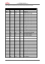
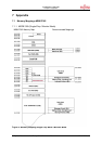
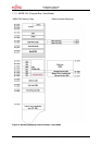
Also refer to the detailed memory maps in the appendix.
Always check the “map”-file (use the context menu in the project-view and select “open
list file”) to see the used sections and addresses !