


STARTERKIT MB91360
Chapter 1 Introduction
UG-910006-13 - 6 - © Fujitsu Microelectronics Europe GmbH
1 Introduction
1.1 Abstract
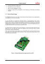
The Fujitsu MB91360 evaluation board is a stand-alone application board that makes it easy
to evaluate and demonstrate almost all features of the MB91360 microcontroller series.
Along with the supplied Windows-based development tools, it can be used as a system for
user program developments.
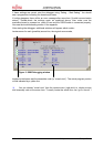
The board can be configured as a target for the MB91360 emulation-system or as a stand-
alone evaluation unit. When using the system in stand-alone mode, a monitor debugger is
available to allow high-level debugging using Softune Workbench.
All peripheral functions are available on external pin-headers in order to design and test user
applications cost- and time-effectively. For some resource functions, additional hardware is
already present on the board (e.g. CAN- and UART-transceivers, LEDs, Buttons, etc).
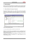
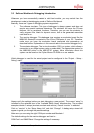
The included Windows-based Software “Softune Workbench” is an integrated front-end for
development and debugging. It allows fast development of “ANSI C”-based applications for
the evaluationboard. To get started quickly, a number of example projects and templates are
available.
Related documents such as “MB91360 Hardware Manual” are available and should always
be used in addition to this manual (see appendix).
1.2 Key Features
< Footprint QFP208 (0.5mm pitch) + socket for MB91F362 (or emulation socket),
surrounded by headers for test-pins etc.
< 4MHz and 32kHz crystal
< DC Power-supply circuit (incl. testpins for Vcc, GND, LED and switch)
< 512kB external SRAM available for user code and data
< External 16550 UART (supports transfer-rates up to 115.2 kBaud)
< 22V10-PAL for various control functions
< Resets (“Monitor”=Start monitor mode, “User”=exec user program from external
RAM, “Flash”=exec user program from flash-ROM)
< MAX232 + DB9 (female) connectors for monitor and internal UART
< CAN tranceiver and DB9 (male) for internal CAN0
< External Interrupt 0 and 1 connected to buttons for user interaction
< Various jumpers for individual configuration
< 2x16 char LCD (on Port G)
< 8 LEDs (on Port J)
< External bus and all resources logically grouped on pin-headers