


Contents
Illustrations
Figures
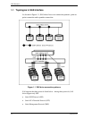
Figure 1.1 SAS drive connection patterns............................................................. 22
Figure 1.2 SAS control layers................................................................................ 23
Figure 1.3 Physical links and phys ........................................................................ 24
Figure 1.4 Ports (narrow ports and wide ports) ..................................................... 25
Figure 1.5 SAS devices ......................................................................................... 26
Figure 1.6 Example of potential pathways ............................................................ 27
Figure 1.7 Reset-related terminology .................................................................... 32
Figure 1.8 OOB signal transmission...................................................................... 34
Figure 1.9 OOB signal detection ........................................................................... 36
Figure 1.10 SAS to SAS OOB sequence................................................................. 37
Figure 1.11 SAS speed negotiation window............................................................ 39
Figure 1.12 SAS speed negotiation sequence (Example 1)..................................... 41
Figure 1.13 SAS speed negotiation sequence (Example 2)..................................... 41
Figure 1.14 Phy reset sequence (Example).............................................................. 42
Figure 1.15 Connection request timeout example ................................................... 69
Figure 1.16 Closing a connection example.............................................................. 70
Figure 1.17 Interlocked frames................................................................................ 75
Figure 1.18 Non-interlocked frames with the same tag........................................... 76
Figure 1.19 Non-interlocked frames with different tags.......................................... 76
Figure 1.20 Closing an SSP connection example.................................................... 77
Figure 1.21 Example of XFER_RDY frames.......................................................... 88
Figure 1.22 Example of TASK frame...................................................................... 96
Figure 1.23 Example of write command ................................................................. 97
Figure 1.24 Example of read command................................................................... 97
Figure 1.25 Example of the processing sequence for an exceptional event ............ 99
Figure 2.1 Data space configuration.................................................................... 124
Figure 3.1 Data buffer configuration (in the case of 8 cache segments) ............. 128
Figure 4.1 MODE SELECT parameter structure................................................. 155
Figure 4.2 Correction of the defect descriptor..................................................... 238
Figure 6.1 Analysis of the termination status ...................................................... 372
Tables
Table 1.1 SAS address format.............................................................................. 29
Table 1.2 Hashed SAS address code parameter................................................... 30
Table 1.3 Usage of special characters .................................................................. 31
Table 1.4 OOB signal timing specifications ........................................................ 33
C141-C013 15