


offered by Busse-Yachtshop.com
7. INSTALLATION
7-5
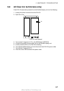
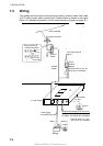
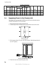
Power cable
Connect the power cable (supplied) to the power source; white wire to positive
[+] terminal and black wire to negative [-] terminal.
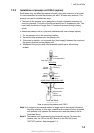
Ground wire
Ground the equipment to prevent noise and interference and enable reception of
weak signals. Run the ground wire (local supply) between the ground terminal
on the facsimile receiver and the ship's grounding bus.
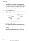
Preamp unit
Connect its coaxial cable directly to the antenna connector on the FAX-30. Note
that an extension cable kit (option) is available, in lengths of 10, 20, 30, 40 and
50 m.
Wire or whip antenna
A junction box or antenna switch (local supply) is required since the connection
at the FAX-30 is made with a coaxial cable. Connect a feeder wire between the
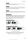
antenna and the junction box or antenna switch. Attach coaxial connector
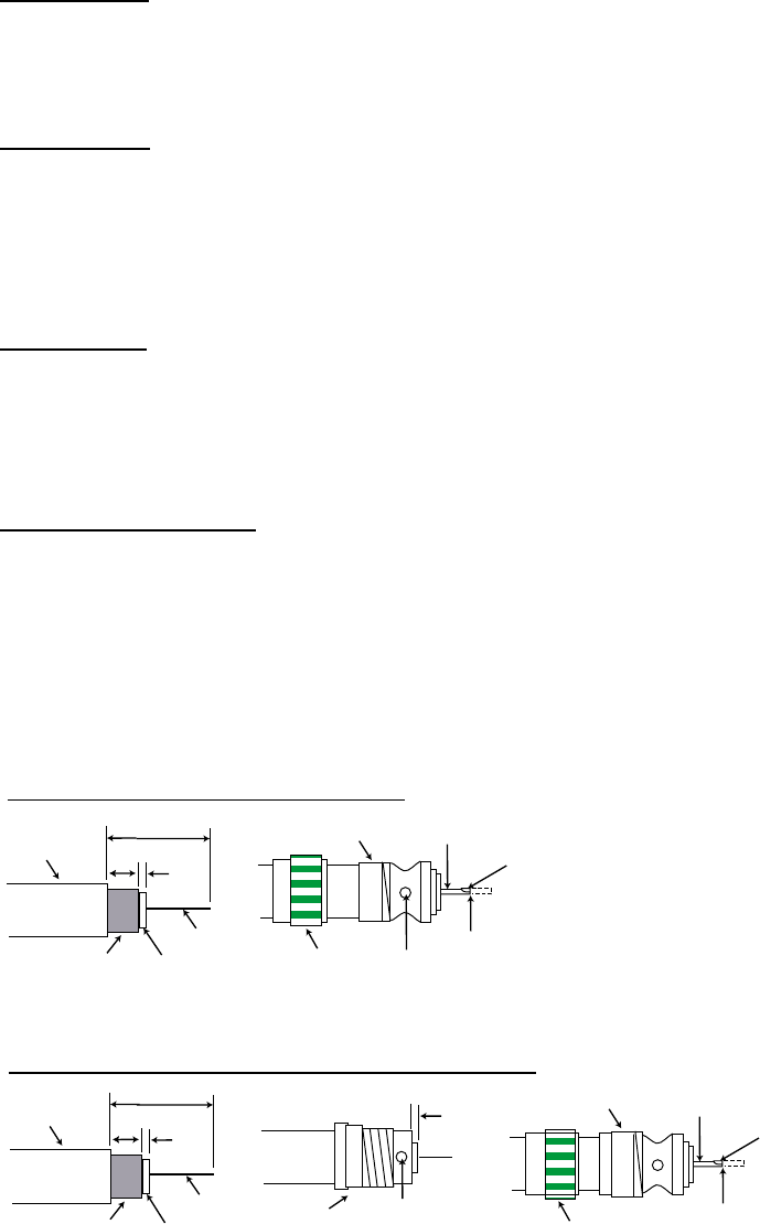
(option) to a 50 ohm coaxial cable as below and connect the cable between the
junction box and the FAX-30. If the connector does not fit the cable, use
appropriate adaptor (option).
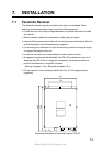
Cable type 7C-2V, RG-8/U, RG-213/U, etc.
Cable type 5D-2V, 5C-2V, RG-5/U, 3C-2V, RG-58/U, etc.
Sheath
30 mm
5 mm
2 mm
Conductor
Insulator
Braided
shield
Plug assembly
Contact sleeve
Cut conductor here.
Solder both
sides of hole.
Coupling
ring
Solder here.
Sheath
30 mm
7 mm
3.5
mm
Conductor
Insulator
Braided
shield
Solder both
sides of hole.
Reducer
Screw tightly.
Contact sleeve
Cut conductor here.
Coupling
ring
Solder here.
3.5 mm
Attachment of antenna connector
Note: The cables 3C-2V, 5C-2V, 5D-2V and 7C-2V are JIS (Japan Industry
Standard) cables. If these are not available use equivalent cables,
referring to the table on the next page for specifications.